
https://www.raspberrypi.com/documentation/computers/configuration.html
CHECKOUT: Configuring networking
Configuration
The raspi-config Tool
Edit this on GitHub
raspi-config is the Raspberry Pi configuration tool, originally written by Alex Bradbury. To open the configuration tool, type the following on the command line:
sudo raspi-config
The sudo is required because you will be changing files that you do not own as the regular user.
| NOTE | If you are using the Raspberry Pi desktop, you can use the graphical Raspberry Pi Configuration application from the Preferences menu to configure your Raspberry Pi. |
|---|---|
You should then see a blue screen with options in a grey box:

| NOTE | The menu shown may differ slightly. |
|---|---|
Use the up and down arrow keys to move the highlighted selection between the options available. Pressing the right arrow key will jump out of the Options menu and take you to the <Select> and <Finish> buttons. Pressing left will take you back to the options. Alternatively, you can use the Tab key to switch between these.
Generally speaking, raspi-config aims to enable the user to make the most common configuration changes. This may result in automated edits to /boot/firmware/config.txt and various standard Linux configuration files. Some options require a reboot to take effect. If you changed any of these, raspi-config will ask if you wish to reboot when you select the <Finish> button.
| NOTE | In long lists of option values (like the list of timezone cities), you can also type a letter to skip to that section of the list. For example, entering L will skip you to Lisbon, just two options away from London, to save you scrolling all the way through the alphabet. |
|---|---|
List of options
| NOTE | Due to the continuous development of the raspi-config tool, the list of options below may not be completely up-to-date. Also please be aware that different models of Raspberry Pi may have different options available. |
|---|---|
| NOTE | All options are available via a non-interactive command line interface. See the section on the raspi-config command line interface for more information. |
|---|---|
System options
The system options submenu allows you to make configuration changes to various parts of the boot, login and networking process, along with some other system level changes.

Wireless LAN
Allows setting of the wireless LAN SSID and passphrase.
Audio
Specify the audio output destination.
Password
You can change the 'default' user password.
| NOTE | Originally, the default user on early versions of Raspberry Pi OS was pi with the password raspberry. The default user is now set while configuring the OS image or on first boot using a configuration wizard. |
|---|---|
Hostname
Set the visible name for this Raspberry Pi on a network.
Boot/auto login
From this submenu you can select whether to boot to console or desktop, and whether you need to log in or not. If you select automatic login, you will be logged in with your current username.
Network at boot
Use this option to wait for a network connection before letting boot proceed.
Splash screen
Enable or disable the splash screen displayed at boot time
Power LED
If the model of Raspberry Pi you are using permits it, you can change the behaviour of the power LED using this option.
Browser
Use this option to change the default web browser. Choosing a web browser that isn’t currently installed won’t work.
Display options

Underscan
| NOTE | This option isn’t available if you’re using the Wayland backend. |
|---|---|
If the initial text shown on the screen disappears off the edge, you need to enable overscan to bring the border back. On some displays, particularly monitors, disabling overscan will make the picture fill the whole screen and will remove the black border.
Screen blanking
Enable or disable screen blanking.
VNC resolution
Define the video resolution to use in headless setups.
Composite
Enable or disable composite video.
4Kp60 HDMI
Enable or disable 4Kp60 resolution for HDMI outputs.
Interface options
In this submenu there are the following options to enable/disable: SSH, VNC, SPI, I2C, Serial port, 1-wire, and Remote GPIO.

SSH
Enable/disable remote command-line access to your Raspberry Pi using SSH.
SSH allows you to remotely access the command line of the Raspberry Pi from another computer. SSH is disabled by default. Read more about using SSH on the SSH documentation page. If connecting your Raspberry Pi directly to a public network, you should not enable SSH unless you have set up secure passwords for all users.
VNC
Enable/disable the WayVNC or RealVNC virtual network computing server.
SPI
Enable/disable SPI interfaces and automatic loading of the SPI kernel module.
I2C
Enable/disable I2C interfaces and automatic loading of the I2C kernel module.
Serial port
Enable/disable shell and kernel messages on the serial connection.
1-Wire
Enable/disable the Dallas 1-wire interface. This is usually used for DS18B20 temperature sensors.
Remote GPIO
Enable or disable remote access to the GPIO pins.
Performance options

Overclock
On some models it is possible to overclock your Raspberry Pi’s CPU using this tool. The overclocking you can achieve will vary; overclocking too high may result in instability. Selecting this option shows the following warning:
Be aware that overclocking may reduce the lifetime of your Raspberry Pi. If overclocking at a certain level causes system instability, try a more modest overclock. Hold down the Shift key during boot to temporarily disable overclocking.
GPU memory
Change the amount of memory made available to the GPU.
Overlay file system
Enable or disable a read-only filesystem.
Fan
Set the behaviour of a GPIO connected fan.
Localisation options
The localisation submenu gives you these options to choose from: keyboard layout, time zone, locale, and wireless LAN country code.

Locale
Select a locale, for example en_GB.UTF-8 UTF-8.
Time zone
Select your local time zone, starting with the region, e.g. Europe, then selecting a city, e.g. London. Type a letter to skip down the list to that point in the alphabet.
Keyboard
This option opens another menu which allows you to select your keyboard layout. Changes usually take effect immediately, but may require a reboot.
WLAN country
This option sets the country code for your wireless network.
Advanced options

| NOTE | The options documented here will change depending on the model of Raspberry Pi that you’re using, and whether you’re using the Wayland or X11 backend. In the current version of Raspberry Pi OS Bookworm, the Raspberry Pi 4 and Pi 400 use Wayland by default; other models of Raspberry Pi use X11 by default. |
|---|---|
Expand filesystem
This option will expand your installation to fill the whole SD card, giving you more space to use for files. You will need to reboot the Raspberry Pi to make this available.
| WARNING | There is no confirmation step: selecting the option begins the partition expansion immediately. |
|---|---|
Network interface names
Enable or disable predictable network interface names.
Network proxy settings
Configure the network’s proxy settings.
Boot order
On Raspberry Pi 4, you can specify whether to boot from USB or network if the SD card isn’t inserted. See this page for more information.
Bootloader version
On the Raspberry Pi 4, you can tell the system to use the very latest boot ROM software, or revert to the factory default if the latest version causes problems.
Wayland
Use this option to switch between the X11 and Wayland backends. The Wayland backend was introduced in Bookworm, X11 was used in older versions of Raspberry Pi OS.
Audio config
Use this option to switch between the PulseAudio and PipeWire audio backends. The PipeWire backend was introduced in Bookworm. PulseAudio was used in older versions of Rasperry Pi OS.
Update
Update this tool to the latest version.
About raspi-config
Selecting this option shows the following text:
This tool provides a straightforward way of doing initial configuration of the Raspberry Pi.
Although it can be run at any time, some of the options may have difficulties if you have heavily customised your installation.
Finish
Use this option when you have completed your changes. You will be asked whether you want to reboot or not. When implementing changes for the first time, it’s best to reboot. There will be a delay in rebooting if you have chosen to resize your SD card.
The raspi-config Command Line Interface
The raspi-config tool can also be run in a non-interactive mode, which is useful for setting up a Raspberry Pi image for distribution.
sudo raspi-config nonint <command> <arguments>
The sudo is required because you will be changing files that are not owned by the default user.
| NOTE | There is no consistent meaning for 0 and 1 in arguments. Each function will document what 0 and 1 mean for that particular function. |
|---|---|
List of options
| NOTE | The raspi-config tool is under continuous development, and the list of options below may not be completely up to date. Please be aware that different models of Raspberry Pi may have different options available. |
|---|---|
System options
Wireless LAN
Allows setting of the wireless LAN SSID and passphrase.
sudo raspi-config nonint do_wifi_ssid_passphrase <ssid> <passphrase> [hidden] [plain]
Hidden: 0 = visible, 1 = hidden. Defaults to visible.
Plain: If plain is 1 (the default), the passphrase is quoted.
Example:
sudo raspi-config nonint do_wifi_ssid_passphrase myssid mypassphrase
sudo raspi-config nonint do_wifi_ssid_passphrase myssid mypassphrase 1 # Hidden SSID
sudo raspi-config nonint do_wifi_ssid_passphrase myssid '"mypassphrase"' 0 0 # Visible SSID, passphrase quoted
Audio
Specify the audio output destination.
sudo raspi-config nonint do_audio <N>
Raspberry Pi 4B+
0– bcm2835 Headphones1– vc4-hdmi-02– vc4-hdmi-1
| NOTE | You may need to run the interactive version of raspi-config to determine the appropriate numbers to use with this option. |
|---|---|
Password
You can change the 'default' user password.
| NOTE | Under old versions of Raspberry Pi OS, the default user was pi with the password raspberry. The default user is now set while configuring the OS image, or on first boot using a configuration wizard. |
|---|---|
sudo raspi-config nonint do_change_pass
| NOTE | This does not check for the interactive flag, and will show full-screen messages. |
|---|---|
Hostname
Set the visible name for this Raspberry Pi on a network.
sudo raspi-config nonint do_hostname <hostname>
Boot/auto login
Select whether to boot to console or desktop and whether you need to log in or not.
sudo raspi-config nonint do_boot_behaviour <B1/B2/B3/B4>
B1– Boot to console, requiring loginB2– Boot to console, logging in automaticallyB3– Boot to desktop, requiring loginB4– Boot to desktop, logging in automatically
Network at boot
Use this option to wait for a network connection before letting boot proceed.
sudo raspi-config nonint do_boot_wait <0/1>
0– Boot without waiting for network connection1– Boot after waiting for network connection
Splash screen
Enable or disable the splash screen displayed at boot time.
sudo raspi-config nonint do_boot_splash <0/1>
0– Enable splash screen1– Disable splash screen
Power LED
If the model of Raspberry Pi permits it, you can change the behaviour of the power LED using this option.
sudo raspi-config nonint do_leds <0/1>
0– Flash for disk activity1– Be on constantly
Browser
Change the default web browser. Choosing a web browser that isn’t currently installed won’t work.
sudo raspi-config nonint do_browser <chromium-browser/firefox>
Display options
Underscan
If the initial text shown on the screen disappears off the edge, you need to enable overscan to bring the border back. On some displays, particularly monitors, disabling overscan will make the picture fill the whole screen and remove the black border.
sudo raspi-config nonint do_overscan_kms <device> <enabled>
Device: 1 = HDMI-1, 2 = HDMI-2
Enabled: 0 = Enable overscan, 1 = Disable overscan
Screen blanking
Enable or disable screen blanking.
sudo raspi-config nonint do_blanking <0/1>
0– Enable screen blanking1– Disable screen blanking
VNC resolution
Define the video resolution to use in headless setups.
sudo raspi-config nonint do_vnc_resolution <width>x<height>
Composite
Enable or disable composite video output.
On Raspberry Pi 4, use:
sudo raspi-config nonint do_pi4video <V1/V2/V3>
V1– Enable 4Kp60 HDMI outputV2– Enable composite video outputV3– Disable 4Kp60 and composite output
On models prior to the Raspberry Pi 4, use:
sudo raspi-config nonint do_composite <0/1>
0– Enable composite video1– Disable composite video
Interface options
SSH
Enable/disable remote command line access to your Raspberry Pi using SSH.
SSH allows you to remotely access the command line of the Raspberry Pi from another computer. SSH is disabled by default. Read more about using SSH on the SSH documentation page. If connecting your Raspberry Pi directly to a public network, you should not enable SSH unless you have set up secure passwords for all users.
sudo raspi-config nonint do_ssh <0/1>
0– Enable SSH1– Disable SSH
VNC
Enable/disable a virtual network computing server.
sudo raspi-config nonint do_vnc <0/1>
0– Enable VNC1– Disable VNC
SPI
Enable/disable SPI interfaces and automatic loading of the SPI kernel module.
sudo raspi-config nonint do_spi <0/1>
0– Enable SPI1– Disable SPI
I2C
Enable/disable I2C interfaces and automatic loading of the I2C kernel module.
sudo raspi-config nonint do_i2c <0/1>
0– Enable I2C1– Disable I2C
Serial Port
Enable/disable the serial connection hardware.
sudo raspi-config nonint do_serial_hw <0/1/2>
0– Enable serial port1– Disable serial port
Serial console
Enable/disable shell and kernel messages on the serial connection.
raspi-config nonint do_serial_cons <0/1/2>
0– Enable console over serial port1– Disable console over serial port
1-wire
Enable/disable the Dallas 1-wire interface. This is usually used for DS18B20 temperature sensors.
sudo raspi-config nonint do_onewire <0/1>
0– Enable 1-wire1– Disable 1-wire
Remote GPIO
Enable or disable remote access to the GPIO pins.
sudo raspi-config nonint do_rgpio <0/1>
0– Enable remote GPIO1– Disable remote GPIO
Performance options
Overclock
On some models it is possible to overclock your Raspberry Pi’s CPU using this tool. The overclocking you can achieve will vary, and overclocking too high may result in instability. Selecting this option shows the following warning:
Be aware that overclocking may reduce the lifetime of your Raspberry Pi. If overclocking at a certain level causes system instability, try a more modest overclock. Hold down the Shift key during boot to temporarily disable overclocking.
sudo raspi-config nonint do_overclock <setting>
Setting is one of:
None– The defaultModest– Overclock to 50% of the maximumMedium– Overclock to 75% of the maximumHigh– Overclock to 100% of the maximumTurbo– Overclock to 125% of the maximum
GPU memory
Change the amount of memory made available to the GPU.
sudo raspi-config nonint do_memory_split <megabytes>
Overlay file system
Enable or disable a read-only filesystem.
sudo raspi-config nonint do_overlayfs <0/1>
0– Enable overlay filesystem1– Disable overlay filesystem
Fan
Set the behaviour of a GPIO connected fan.
sudo raspi-config nonint do_fan <0/1> [gpio] [onTemp]
0– Enable fan1– Disable fan
gpio defaults to 14.
onTemp defaults to 80 °C.
Localisation options
Locale
Select a locale, for example en_GB.UTF-8 UTF-8.
sudo raspi-config nonint do_change_locale <locale>
Time zone
Select your local time zone, starting with the region, e.g. Europe, then selecting a city, e.g. London. Type a letter to skip down the list to that point in the alphabet.
sudo raspi-config nonint do_change_timezone <timezone>
sudo raspi-config nonint do_change_timezone America/Los_Angeles
Keyboard
This option opens another menu which allows you to select your keyboard layout. Changes usually take effect immediately, but may require a reboot.
sudo raspi-config nonint do_configure_keyboard <keymap>
sudo raspi-config nonint do_configure_keyboard us
WLAN country
This option sets the country code for your wireless network.
sudo raspi-config nonint do_wifi_country <country>
sudo raspi-config nonint do_wifi_country US
Advanced options
Expand filesystem
This option will expand your installation to fill the whole SD card, giving you more space to use for files. You will need to reboot the Raspberry Pi to make this available.
| WARNING | There is no confirmation step: selecting the option begins the partition expansion immediately. |
|---|---|
sudo raspi-config nonint do_expand_rootfs
Network interface names
Enable or disable predictable network interface names.
sudo raspi-config nonint do_net_names <0/1>
0– Enable predictable network interface names1– Disable predictable network interface names
Network proxy settings
Configure the network’s proxy settings.
sudo raspi-config nonint do_proxy <SCHEMES> <ADDRESS>
Boot order
On the Raspberry Pi 4, you can specify whether to boot from USB or network if the SD card isn’t inserted. See the bootloader configuration section for more information.
sudo raspi-config nonint do_boot_order <B1/B2/B3>
B1– SD card boot – boot from SD card if available, otherwise boot from USBB2– USB boot – boot from USB if available, otherwise boot from SD cardB3– Network boot – boot from network if SD card boot fails
Bootloader version
On Raspberry Pi 4 and 5, you can tell the system to use the very latest boot ROM software, or revert to the factory default if the latest version causes problems.
sudo raspi-config nonint do_boot_rom <E1/E2>
E1– Use the latest boot ROME2– Use the factory default
Wayland
Use this option to switch between the X11 and Wayland backends. On the Raspberry Pi 4 and 5, Wayland is used by default; on other models of Raspberry Pi, X11 is used by default.
sudo raspi-config nonint do_wayland <W1/W2>
W1– Use the X11 backendW2– Use the Wayland backend
Audio config
Use this option to switch between the PulseAudio and PipeWire audio backends.
sudo raspi-config nonint do_audioconf <1/2>
1– Use the PulseAudio backend2– Use the PipeWire backend
Update
Update this tool to the latest version.
sudo raspi-config nonint do_update
Configuring networking
Edit this on GitHub
Raspberry Pi OS provides a graphical user interface (GUI) for setting up wireless connections. Users of Raspberry Pi OS Lite and headless machines can set up wireless networking from the command line with nmcli.
| NOTE | Network Manager is the default networking configuration tool under Raspberry Pi OS Bookworm or later. While Network Manager can be installed on earlier versions of the operating system using apt and configured as the default using raspi-config, earlier versions used dhcpd and other tools for network configuration by default. |
|---|---|
Using the desktop
Access Network Manager via the network icon at the right-hand end of the menu bar. If you are using a Raspberry Pi with built-in wireless connectivity, or if a wireless dongle is plugged in, click this icon to bring up a list of available wireless networks. If you see the message 'No APs found – scanning…', wait a few seconds, and Network Manager should find your network.
| NOTE | Raspberry Pi devices that support dual-band wireless (Raspberry Pi 3B+, Raspberry Pi 4, Compute Module 4, Raspberry Pi 400 and Raspberry Pi 5) automatically disable networking until a you assign a wireless LAN country. To set a wireless LAN country, open the Raspberry Pi Configuration application from the Preferences menu, select Localisation and select your country from the menu. |
|---|---|

The icons on the right show whether a network is secured or not, and give an indication of signal strength. Click the network that you want to connect to. If the network is secured, a dialogue box will prompt you to enter the network key:

Enter the key and click OK, then wait a couple of seconds. The network icon will flash briefly to show that a connection is being made. When connected, the icon will stop flashing and show the signal strength.
Connect to a hidden network
If you want to use a hidden network, use the Advanced options > Connect to a hidden Wi-Fi network in the network menu:

Then, enter the SSID for the hidden network. Ask your network administrator which type of security your network uses; while most home networks currently use WPA and WPA2 personal security, public networks sometimes use WPA and WPA2 enterprise security. Select the security type for your network, and enter your credentials:

Click the Connect button to initiate the network connection.
Using the command line
This guide will help you configure a wireless connection on your Raspberry Pi from a terminal without using graphical tools. No additional software is required.
| NOTE | This guide should work for WEP, WPA, WPA2, or WPA3 networks, but may not work for enterprise networks. |
|---|---|
Enable wireless networking
On a fresh install, you must specify the country where you use your device. This allows your device to choose the correct frequency bands for 5GHz networking. Once you have specified a wireless LAN country, you can use your Raspberry Pi’s built-in wireless networking module.
To do this, set your wireless LAN country with the command line raspi-config tool. Run the following command:
sudo raspi-config
Select the Localisation options menu item using the arrow keys. Choose the WLAN country option. Pick your country from the dropdown using the arrow keys. Press Enter to select your country.
You should now have access to wireless networking. Run the following command to check if your Wi-Fi radio is enabled:
nmcli radio wifi
If this command returns the text "enabled", you’re ready to configure a connection. If this command returns "disabled", try enabling Wi-Fi with the following command:
nmcli radio wifi on
Find networks
To scan for wireless networks, run the following command:
nmcli dev wifi list
You should see output similar to the following:
IN-USE  BSSID              SSID            MODE   CHAN  RATE        SIGNAL  BARS  SECURITY
        90:72:40:1B:42:05  myNetwork       Infra  132   405 Mbit/s  89      ****  WPA2
        90:72:42:1B:78:04  myNetwork5G     Infra  11    195 Mbit/s  79      ***   WPA2
        9C:AB:F8:88:EB:0D  Pi Towers       Infra  1     260 Mbit/s  75      ***   WPA2 802.1X
        B4:2A:0E:64:BD:BE  Example         Infra  6     195 Mbit/s  37      **    WPA1 WPA2
Look in the "SSID" column for the name of the network you would like to connect to. Use the SSID and a password to connect to the network.
Connect to a network
Run the following command to configure a network connection:
sudo nmcli --ask dev wifi connect <example_ssid>
Don’t forget to replace <example_ssid> with the name of the network you’re trying to configure.
Enter your network password when prompted.
Your Raspberry Pi should automatically connect to the network once you enter your password. If you see the following output:
Error: Connection activation failed: Secrets were required, but not provided.
This means that you entered an incorrect password. If you see this error, run the above command again, being careful to enter your password correctly.
To check if you’re connected to a network, run the following command:
nmcli dev wifi list
You should see output similar to the following:
IN-USE  BSSID              SSID            MODE   CHAN  RATE        SIGNAL  BARS  SECURITY
*       90:72:40:1B:42:05  myNetwork       Infra  132   405 Mbit/s  89      ****  WPA2
        90:72:42:1B:78:04  myNetwork5G     Infra  11    195 Mbit/s  79      ***   WPA2
        9C:AB:F8:88:EB:0D  Pi Towers       Infra  1     260 Mbit/s  75      ***   WPA2 802.1X
        B4:2A:0E:64:BD:BE  Example         Infra  6     195 Mbit/s  37      **    WPA1 WPA2
Check for an asterisk (*) in the "IN-USE" column; it should appear in the same row as the SSID of the network you intended to connect to.
| NOTE | You can manually edit your connection configurations in the /etc/NetworkManager/system-connections/ directory. |
|---|---|
Connect to an unsecured network
If the network you are connecting to does not use a password, run the following command:
sudo nmcli dev wifi connect <example_ssid>
| WARNING | Be careful when using unsecured wireless networks. |
|---|---|
Connect to a hidden network
If you are using a hidden network, specify the "hidden" option with a value of "yes" when you run nmcli:
sudo nmcli --ask dev wifi connect <example_ssid> hidden yes
Set priority among multiple networks
If your device detects more than one known networks at the same time, it could connect any of the detected known networks. Use the priority option to force your Raspberry Pi to prefer certain networks. Your device will connect to the network that is in range with the highest priority. Run the following command to view the priority of known networks:
nmcli --fields autoconnect-priority,name connection
You should see output similar to the following:
AUTOCONNECT-PRIORITY  NAME
0                     myNetwork
0                     lo
0                     Pi Towers
0                     Example
-999                  Wired connection 1
Use the nmcli connection modify command to set the priority of a network. The following example command sets the priority of a network named "Pi Towers" to 10:
nmcli connection modify "Pi Towers" connection.autoconnect-priority 10
Your device will always try to connect to the in-range network with the highest non-negative priority value. You can also assign a network a negative priority; your device will only attempt to connect to a negative priority network if no other known network is in range. For example, consider three networks:
AUTOCONNECT-PRIORITY  NAME
-1                    snake
0                     rabbit
1                     cat
1000                  dog
- If all of these networks were in range, your device would first attempt to connect to the "dog" network.
- If connection to the "dog" network fails, your device would attempt to connect to the "cat" network.
- If connection to the "cat" network fails, your device would attempt to connect to the "rabbit" network.
- If connection to the "rabbit" network fails, and your device detects no other known networks, your device will attempt to connect to the "snake" network.
Configure DHCP
By default, Raspberry Pi OS attempts to automatically configure all network interfaces by DHCP, falling back to automatic private addresses in the range 169.254.0.0/16 if DHCP fails.
Assign a static IP address
To allocate a static IP address to your Raspberry Pi, reserve an address for it on your router. Your Raspberry Pi will continue to have its address allocated via DHCP, but will receive the same address each time. A "fixed" address can be allocated by associating the MAC address of your Raspberry Pi with a static IP address in your DHCP server.
Set up a headless Raspberry Pi
Edit this on GitHub
A headless Raspberry Pi runs without a monitor, keyboard, or mouse. To run a Raspberry Pi headless, you need a way to access it from another computer. To access your Raspberry Pi remotely, you’ll need to connect your Raspberry Pi to a network, and a way to access the Raspberry Pi over that network.
To connect your Raspberry Pi to a network, you can either plug your device into a wired connection via Ethernet or configure wireless networking.
To access your Raspberry Pi over that network, use SSH. Once you’ve connected over SSH, you can use raspi-config to enable VNC if you’d prefer a graphical desktop environment.
If you’re setting up your Raspberry Pi from scratch, set up wireless networking and SSH during the imaging process. If you’ve already got a Raspberry Pi set up, you can configure SSH using raspi-config.
| WARNING | Depending on the model of Raspberry Pi and type of SD card you are using, your Raspberry Pi may require up to five minutes to boot and connect to your wireless network the first time it boots. |
|---|---|
Connect to a wired network
To connect to a wired network at first boot, plug your headless Raspberry Pi in via Ethernet, or use an Ethernet adapter if your Raspberry Pi model does not include an Ethernet port. Your Raspberry Pi will automatically connect to the network.
Connect to a wireless network
To configure wireless network access at first boot in a headless Raspberry Pi, use the advanced settings menu in Raspberry Pi Imager. Enter the SSID and password of your preferred wireless network. Your Raspberry Pi will use these credentials to connect to the network on first boot. Some wireless adapters and some Raspberry Pi boards do not support 5GHz networks; check the documentation for your wireless module to ensure compatibility with your preferred network.
| NOTE | Previous versions of Raspberry Pi OS made use of a wpa_supplicant.conf file which could be placed into the boot folder to configure wireless network settings. This functionality is not available from Raspberry Pi OS Bookworm onwards. |
|---|---|
Remote access
With no keyboard or monitor, you need a way to remotely control your headless Raspberry Pi. On first boot, the only option is SSH. To enable SSH on a fresh installation of Raspberry Pi OS, choose one of the following methods:
- enable SSH in the OS customisation menu in Raspberry Pi Imager, then enter a username and password
- create a file named
sshat the root of the SD card, then configure a user manually withuserconf.txtfollowing the instructions in the section below
For more information, see set up an SSH server. Once you’ve connected over SSH, you can use raspi-config to enable VNC if you’d prefer a graphical desktop environment.
Configure a user manually
At the root of your SD card, create a file named userconf.txt.
This file should contain a single line of text, consisting of <username>:<password>: your desired username, followed immediately by a colon, followed immediately by an encrypted representation of the password you want to use.
| NOTE | <username> must only contain lower-case letters, digits and hyphens, and must start with a letter. It may not be longer than 31 characters. |
|---|---|
To generate the encrypted password, use OpenSSL on another computer. Open a terminal and enter the following:
openssl passwd -6
When prompted, enter your password and verify it. This command will then output an encrypted version of the supplied password.
Host a wireless network on your Raspberry Pi
Edit this on GitHub
Your Raspberry Pi can host its own wireless network using a wireless module. If you connect your Raspberry Pi to the internet via the Ethernet port (or a second wireless module), other devices connected to the wireless network can access the internet through your Raspberry Pi.
Consider a wired network that uses the 10.x.x.x IP block. You can connect your Raspberry Pi to that network and serve wireless clients on a separate network that uses another IP block, such as 192.168.x.x.
In the diagram below, note that the laptop exists in an IP block separate from the router and wired clients:

With this network configuration, wireless clients can all communicate with each other through the Raspberry Pi router. However, clients on the wireless network cannot directly interact with clients on the wired network other than the Raspberry Pi; wireless clients exist in a private network separate from the network that serves wired clients.
| NOTE | The Raspberry Pi 5, 4, 3, and Raspberry Pi Zero W can host a wireless network using the built-in wireless module. Raspberry Pi models that lack a built-in module support this functionality using a separate wireless dongle. |
|---|---|
Enable hotspot
To create a hosted wireless network on the command line, run the following command, replacing the <example-network-name> and <example-password> placeholders with your own values:
sudo nmcli device wifi hotspot ssid <example-network-name> password <example-password>
Use another wireless client, such as a laptop or smartphone, to connect to the network. Look for a network with a SSID matching <example-network-name>. Enter your network password, and you should connect successfully to the network. If your Raspberry Pi has internet access via an Ethernet connection or a second wireless adapter, you should be able to access the internet.
Disable hotspot
To disable the hotspot network and resume use of your Pi as a wireless client, run the following command:
sudo nmcli device disconnect wlan0
After disabling the network, run the following command to reconnect to another Wi-Fi network:
sudo nmcli device up wlan0
| TIP | For more information about connecting to wireless networks, see Configuring networking. |
|---|---|
Use your Raspberry Pi as a network bridge
By default, the wireless network hosted from your Raspberry Pi exists separately from the parent network connected via Ethernet. In this arrangement, devices connected to the parent network cannot directly communicate with devices connected to the wireless network hosted from your Raspberry Pi. If you want connected wireless devices to be able to communicate with devices on the parent network, you can configure your Raspberry Pi as a network bridge. With a network bridge in place, each device connected to the Pi-hosted wireless network is assigned an IP address in the parent network.
In the diagram below, note that the laptop exists in the same IP block as the router and wired clients:
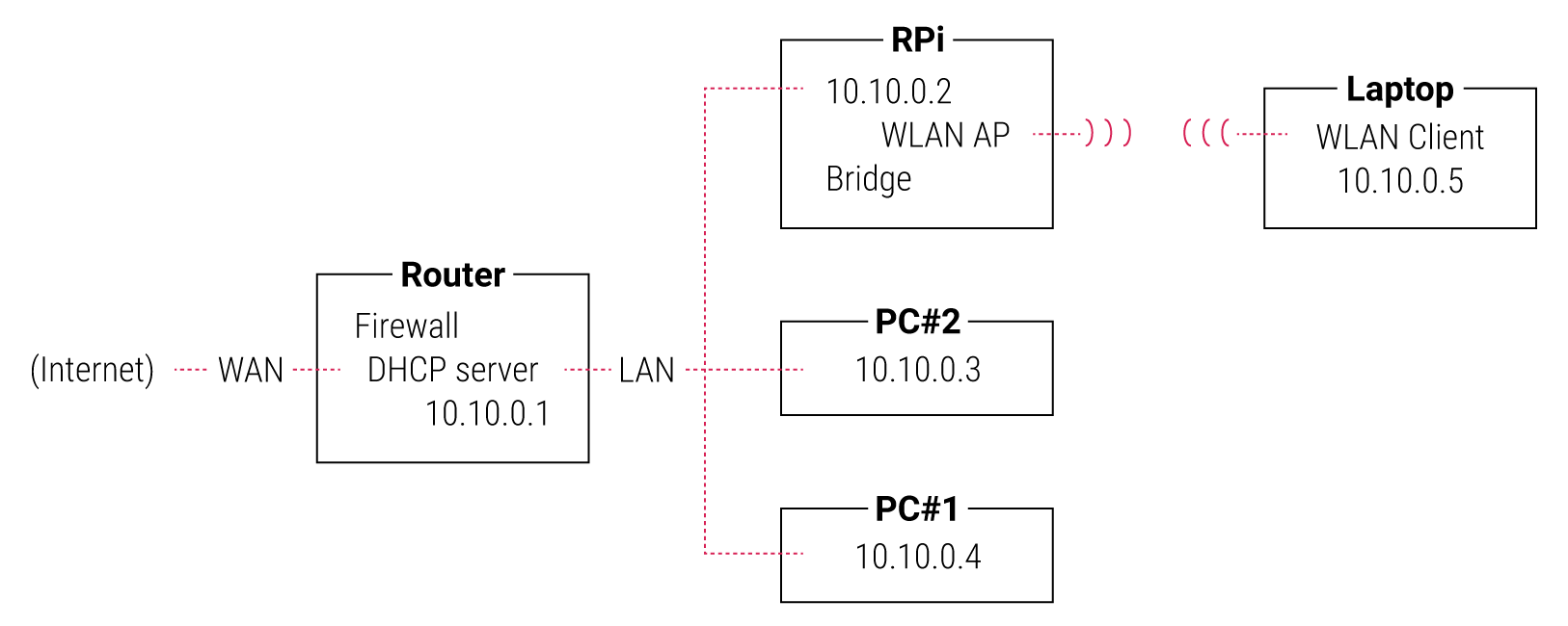
The following steps describe how to set up a network bridge on your Raspberry Pi to enable communication between wireless clients and the parent network.
First, create a network bridge interface:
sudo nmcli connection add type bridge con-name 'Bridge' ifname bridge0
Next, add your device’s Ethernet connection to the parent network to the bridge:
sudo nmcli connection add type ethernet slave-type bridge \
    con-name 'Ethernet' ifname eth0 master bridge0
Finally, add your wireless hotspot connection to the bridge. You can either add an existing hotspot interface or create a new one:
If you have already created a wireless hotspot connection using the instructions above, add the existing interface to the bridge with the following command:
sudo nmcli connection modify 'Hotspot' master bridge0If you have not yet created a wireless hotspot connection, create a new interface and add it to the bridge with a single command, replacing the
<hotspot-password>placeholder with a password of your choice:sudo nmcli connection add con-name 'Hotspot' \ ifname wlan0 type wifi slave-type bridge master bridge0 \ wifi.mode ap wifi.ssid Hotspot wifi-sec.key-mgmt wpa-psk \ wifi-sec.proto rsn wifi-sec.pairwise ccmp \ wifi-sec.psk <hotspot-password>
Now that you’ve configured your bridge, it’s time to activate it. Run the following command to activate the bridge:
sudo nmcli connection up Bridge
And run the following command to start hosting your wireless network:
sudo nmcli connection up Hotspot
You can use the nmcli device command to verify that the bridge, Ethernet interface, and wireless hotspot interface are all active.
| TIP | Use a tool such as arp-scan to check if devices on the parent network are accessible once connected to the hotspot. |
|---|---|
Using a proxy server
Edit this on GitHub
If you want your Raspberry Pi to access the internet via a proxy server (perhaps from a school or other workplace), you will need to configure your Raspberry Pi to use the server before you can get online.
You will need:
- The IP address or hostname and port of your proxy server
- A username and password for your proxy (if required)
Configuring your Raspberry Pi
You will need to set up three environment variables (http_proxy, https_proxy, and no_proxy) so your Raspberry Pi knows how to access the proxy server.
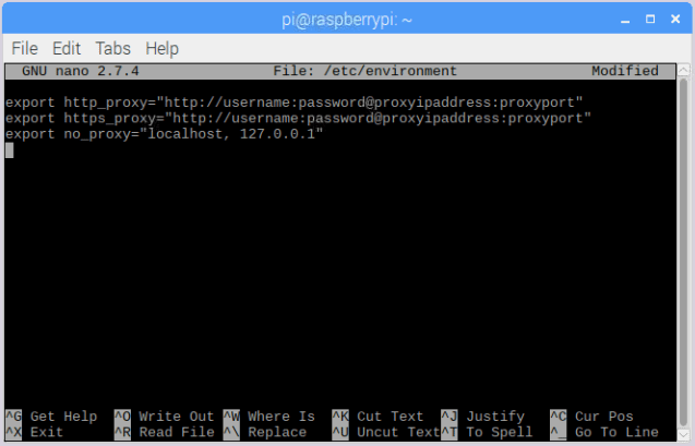
Open a terminal window, and open the file /etc/environment using nano:
sudo nano /etc/environment
Add the following to the /etc/environment file to create the http_proxy variable:
export http_proxy="http://proxyipaddress:proxyport"
Replace proxyipaddress and proxyport with the IP address and port of your proxy.
| NOTE | If your proxy requires a username and password, add them using the following format: |
|---|---|
export http_proxy="http://username:password@proxyipaddress:proxyport"
Enter the same information for the environment variable https_proxy:
export https_proxy="http://username:password@proxyipaddress:proxyport"
Create the no_proxy environment variable, which is a comma-separated list of addresses your Raspberry Pi should not use the proxy for:
export no_proxy="localhost, 127.0.0.1"
Your /etc/environment file should now look like this:
export http_proxy="http://username:password@proxyipaddress:proxyport"
export https_proxy="http://username:password@proxyipaddress:proxyport"
export no_proxy="localhost, 127.0.0.1"
Press Ctrl + X to save and exit.
Update the sudoers file
In order for operations that run as sudo (e.g. downloading and installing software) to use the new environment variables, you’ll need to update sudoers.
Use the following command to open sudoers:
sudo visudo
Add the following line to the file so sudo will use the environment variables you just created:
Defaults env_keep+="http_proxy https_proxy no_proxy"

Press Ctrl + X to save and exit.
Reboot your Raspberry Pi
Reboot your Raspberry Pi for the changes to take effect. You should now be able to access the internet via your proxy server.
HDMI configuration
Edit this on GitHub
In the vast majority of cases, simply plugging your HDMI-equipped monitor into the Raspberry Pi using a standard HDMI cable will result in the Raspberry Pi automatically using the best resolution the monitor can support. The Raspberry Pi Zero, Zero W and Zero 2 W use a mini HDMI port, so you will need a mini-HDMI-to-full-size-HDMI lead or adapter. On Raspberry Pi 4, Raspberry Pi 5 and Raspberry Pi 400 there are two micro HDMI ports, so you will need a micro-HDMI-to-full-size-HDMI lead or adapter for each display you wish to attach. You should connect any HDMI leads before turning on the Raspberry Pi.
Raspberry Pi 5, Raspberry Pi 4 (and Pi 400) can drive up to two displays, with a resolution up to 1080p at a 60Hz refresh rate. At 4K resolution, if you connect two displays then you are limited to a 30Hz refresh rate. You can also drive a single display at 4K with a 60Hz refresh rate: this requires that the display is attached to the HDMI port adjacent to the USB-C power input (labelled HDMI0). You must also enable 4Kp60 output by setting the hdmi_enable_4kp60=1 flag in config.txt.
The Screen Configuration tool (arandr) is a graphical tool for selecting display modes and setting up multiple displays. You can find this tool in the desktop Preferences menu. Use the Layout menu option to select the screen, resolution, and orientation. If you’re using a multi-screen setup, drag around the displays to any position you want. When you are happy with your setup, click the Apply button to apply the settings.
Setting your display’s resolution and rotation
Edit this on GitHub
If you find yourself in a situation where the Raspberry Pi may not be able to determine the best mode, or you specifically wish to set a non-default resolution, you can set the resolution or rotation manually. The method for doing this depends on whether you’re booting to the desktop environment or booting to the CLI (text console).
Setting the desktop environment resolution and rotation
If you are using the Raspberry Pi desktop, the resolution or rotation is most easily changed by selecting the Screen Configuration utility from the desktop Preferences menu. This will bring up a graphical representation of the display or displays connected to the Raspberry Pi. Right click on the display you wish to modify, and select the required option(s) before clicking Apply.
| NOTE | If you are using the X11 backend, you need to ensure that you close the Screen Configuration utility in order to save the changes you’ve made. If you don’t do this, the changes you made will be forgotten when you reboot. |
|---|---|
It is also possible to change these settings by editing config files, although the method for doing this depends on whether you’re running the Wayland or X11 backend. Open a Terminal window and type:
ps ax | grep [w]ayfire
If you see /usr/bin/wayfire displayed then you’re running Wayland; and if you get no output you’re running X11.
| NOTE | In the current version of Raspberry Pi OS Bookworm, Raspberry Pi 5, Raspberry Pi 4 and Raspberry Pi 400 default to using Wayland to display the desktop environment. Earlier models of Raspberry Pi default to using X11 to display the desktop environment. |
|---|---|
Manually setting the desktop environment resolution and rotation for Wayland
Under Wayland you can set a custom display resolution by editing the .config/wayfire.ini file in your home directory. You need to edit the existing [output:<device>] section, or add a new [output:<device>] section for your display device if one doesn’t exist. For example:
[output:HDMI-A-1]
mode = 1920x1080@60
The <device> part of the output: line (HDMI-A-1 in the example shown here) matches the display options described for KMS.
The mode line is similar to that used by KMS, but slightly different. Consult the Wayfire documentation for more extensive information.
You can also rotate your display by adding a transform line like:
[output:HDMI-A-1]
mode = 1920x1080@60
transform = 270
where the allowable transform options are: normal, 90, 180 and 270.
If you’ve set Raspberry Pi OS to boot to desktop but are not using auto-login, then you’ll also need to edit /usr/share/greeter.ini, which determines the resolution and rotation used by the login screen. This file has the same format as .config/wayfire.ini described earlier, so again you’ll need to add or edit the [output:<device>] section.
Setting the text console resolution and rotation
This is achieved by editing the KMS settings – see configuring the kernel command line for more details.
| NOTE | If you have multiple screens connected, they must all be set to the same rotation value in console mode, or no rotation will be applied. |
|---|---|
Audio configuration
Edit this on GitHub
The Raspberry Pi has up to three audio output modes: HDMI 1 and 2, and a headphone jack. You can switch between these modes at any time.
| NOTE | Audio output over HDMI will provide better sound quality than audio output over the headphone jack. |
|---|---|
If your HDMI monitor or TV has built-in speakers, the audio can be played over the HDMI cable, but you can switch it to a set of headphones or other speakers plugged into the headphone jack. If your display has integrated speakers, audio output is via HDMI by default. Otherwise, it is played via the headphone jack. If this is not your desired output setup, or if the auto-detection is inaccurate, you can manually switch the output.
Changing the audio output
There are two ways of setting the audio output: using the desktop volume control, or using the raspi-config command-line tool.
Desktop volume control
Right-clicking the volume icon on the desktop taskbar brings up the audio output selector, allowing you to choose between the internal audio outputs. It also allows you to select any external audio devices, such as USB sound cards and Bluetooth audio devices. A tick is shown against the currently selected audio output device. Left-click the desired output in the pop-up menu to change this setting.
Pro Audio profile
You may see a device profile named Pro Audio when viewing an audio device on the system tray. This profile exposes the maximum number of channels across every audio device, allowing you greater control over the routing of signals. Unless you have a specific use-case in mind for this type of control, we recommend using a different device profile.
For more information about the Pro Audio profile, visit PipeWire’s FAQ.
Using raspi-config
Open up raspi-config by entering the following into the command line:
sudo raspi-config
This will open the configuration screen:
Select System options (currently option 1, but yours may be different) and press Enter.
Now select the Audio option (currently option S2, but yours may be different) and press Enter.
Select your required mode, press Enter and press the right arrow key to exit the options list, then select Finish to exit the configuration tool.
External storage configuration
Edit this on GitHub
You can connect your external hard disk, SSD, or USB stick to any of the USB ports on the Raspberry Pi, and mount the file system to access the data stored on it.
By default, your Raspberry Pi automatically mounts some of the popular file systems such as FAT, NTFS, and HFS+ at the /media/pi/<HARD-DRIVE-LABEL> location.
| NOTE | Raspberry Pi OS Lite does not implement automounting. |
|---|---|
To set up your storage device so that it always mounts to a specific location of your choice, you must mount it manually.
Mounting a storage device
You can mount your storage device at a specific folder location. It is conventional to do this within the /mnt folder, for example /mnt/mydisk. Note that the folder must be empty.
Plug the storage device into a USB port on the Raspberry Pi, and list all the disk partitions on the Raspberry Pi using the following command:
+
sudo lsblk -o UUID,NAME,FSTYPE,SIZE,MOUNTPOINT,LABEL,MODEL
+ The Raspberry Pi uses mount points / and /boot/firmware/. Your storage device will show up in this list, along with any other connected storage.
Use the SIZE, LABEL, and MODEL columns to identify the name of the disk partition that points to your storage device. For example, sda1. The FSTYPE column contains the filesystem type. If your storage device uses an exFAT file system, install the exFAT driver:
+
 sudo apt update
 sudo apt install exfat-fuse
If your storage device uses an NTFS file system, you will have read-only access to it. If you want to write to the device, you can install the ntfs-3g driver:
+
 sudo apt update
 sudo apt install ntfs-3g
Run the following command to get the location of the disk partition:
+
sudo blkid
+ For example, /dev/sda1.
Create a target folder to be the mount point of the storage device. The mount point name used in this case is mydisk. You can specify a name of your choice:
+
sudo mkdir /mnt/mydisk
Mount the storage device at the mount point you created:
+
sudo mount /dev/sda1 /mnt/mydisk
Verify that the storage device is mounted successfully by listing the contents:
+
ls /mnt/mydisk
Setting up automatic mounting
You can modify the fstab file to define the location where the storage device will be automatically mounted when the Raspberry Pi starts up. In the fstab file, the disk partition is identified by the universally unique identifier (UUID).
Get the UUID of the disk partition:
+
sudo blkid
Find the disk partition from the list and note the UUID. (For example, 5C24-1453.) Open the fstab file using a command line editor such as nano:
+
sudo nano /etc/fstab
Add the following line in the fstab file:
+
UUID=5C24-1453 /mnt/mydisk fstype defaults,auto,users,rw,nofail 0 0
+ Replace fstype with the type of your file system, which you found when you went through the steps above, for example: ntfs.
If the filesystem type is FAT or NTFS, add ,umask=000 immediately after nofail – this will allow all users full read/write access to every file on the storage device.
Now that you have set an entry in fstab, you can start up your Raspberry Pi with or without the storage device attached. Before you unplug the device you must either shut down the Raspberry Pi, or manually unmount it.
| NOTE | If you do not have the storage device attached when the Raspberry Pi starts, it will take an extra 90 seconds to start up. You can shorten this by adding ,x-systemd.device-timeout=30 immediately after nofail. This will change the timeout to 30 seconds, meaning the system will only wait 30 seconds before giving up trying to mount the disk. |
|---|---|
For more information on each Linux command, refer to the specific manual page using the man command. For example, man fstab.
Unmounting a storage device
When the Raspberry Pi shuts down, the system takes care of unmounting the storage device so that it is safe to unplug it. If you want to manually unmount a device, you can use the following command:
sudo umount /mnt/mydisk
If you receive an error that the 'target is busy', this means that the storage device was not unmounted. If no error was displayed, you can now safely unplug the device.
Dealing with 'target is busy'
The 'target is busy' message means there are files on the storage device that are in use by a program. To close the files, use the following procedure.
Close any program which has open files on the storage device. If you have a terminal open, make sure that you are not in the folder where the storage device is mounted, or in a sub-folder of it.
If you are still unable to unmount the storage device, you can use the lsof tool to check which program has files open on the device. You need to first install lsof using apt:
+
 sudo apt update
 sudo apt install lsof
+ To use lsof:
+
lsof /mnt/mydisk
Localising your Raspberry Pi
Edit this on GitHub
You can set your Raspberry Pi up to match your regional settings. Language, keyboard layout and time zone can all be changed using the raspi-config tool.
Change the default pin configuration
Edit this on GitHub
| NOTE | Custom default pin configurations via user-provided Device Tree blobs has been deprecated. |
|---|---|
Device pins during boot sequence
During the bootup sequence, the GPIO pins go through various actions.
- Power-on – pins default to inputs with default pulls, which are described in the datasheet
- Setting by the bootrom
- Setting by
bootcode.bin - Setting by
dt-blob.bin(this page) - Setting by the GPIO command in
config.txt - Additional firmware pins (e.g. UARTS)
- Kernel/Device Tree
On a soft reset, the same procedure applies, except for default pulls, which are only applied on a power-on reset.
It may take a few seconds to run through the process. During this time, the GPIO pins may not be in the state expected by attached peripherals (as defined in dt-blob.bin or config.txt). Since different GPIO pins have different default pulls, you should do one of the following for your peripheral:
- Choose a GPIO pin that defaults to pulls as required by the peripheral on reset
- Delay the peripheral’s startup until the actions are completed
- Add an appropriate pull-up/pull-down resistor
Provide a custom Device Tree blob
In order to compile a Device Tree source (.dts) file into a Device Tree blob (.dtb) file, the Device Tree compiler must be installed by running sudo apt install device-tree-compiler. The dtc command can then be used as follows:
sudo dtc -I dts -O dtb -o /boot/firmware/dt-blob.bin dt-blob.dts
Similarly, a .dtb file can be converted back to a .dts file, if required.
dtc -I dtb -O dts -o dt-blob.dts /boot/firmware/dt-blob.bin
Sections of the dt-blob
The dt-blob.bin is used to configure the binary blob (VideoCore) at boot time. It is not currently used by the Linux kernel. The dt-blob can configure all versions of the Raspberry Pi, including the Compute Module, to use the alternative settings. The following sections are valid in the dt-blob:
videocore
+ This section contains all of the VideoCore blob information. All subsequent sections must be enclosed within this section.
pins_*
+ There are a number of separate pins_* sections, based on particular Raspberry Pi models, namely:
pins_rev1: Rev1 pin setup. There are some differences because of the moved I2C pins.pins_rev2: Rev2 pin setup. This includes the additional codec pins on P5.pins_bplus1: Raspberry Pi 1 Model B+ rev 1.1, including the full 40pin connector.pins_bplus2: Raspberry Pi 1 Model B+ rev 1.2, swapping the low-power and lan-run pins.pins_aplus: Raspberry Pi 1 Model A+, lacking Ethernet.pins_2b1: Raspberry Pi 2 Model B rev 1.0; controls the SMPS via I2C0.pins_2b2: Raspberry Pi 2 Model B rev 1.1; controls the SMPS via software I2C on 42 and 43.pins_3b1: Raspberry Pi 3 Model B rev 1.0pins_3b2: Raspberry Pi 3 Model B rev 1.2pins_3bplus: Raspberry Pi 3 Model B+pins_3aplus: Raspberry Pi 3 Model A+pins_pi0: Raspberry Pi Zeropins_pi0w: Raspberry Pi Zero Wpins_pi02w: Raspberry Pi Zero 2 Wpins_cm: Raspberry Pi Compute Module 1. The default for this is the default for the chip, so it is a useful source of information about default pull-ups/pull-downs on the chip.pins_cm3: Raspberry Pi Compute Module 3pins_cm3plus: Raspberry Pi Compute Module 3+pins_cm4s: Raspberry Pi Compute Module 4Spins_cm4: Raspberry Pi Compute Module 4Each
pins_*section can containpin_configandpin_definessections.
pin_config
+ The pin_config section is used to configure the individual pins. Each item in this section must be a named pin section, such as pin@p32, meaning GPIO32. There is a special section pin@default, which contains the default settings for anything not specifically named in the pin_config section.
pin@pinname
+ This section can contain any combination of the following items:
polarityactive_highactive_low
terminationpull_uppull_downno_pulling
startup_stateactiveinactive
functioninputoutputsdcardi2c0i2c1spispi1spi2smidpipcmpwmuart0uart1gp_clkemmcarm_jtag
drive_strength_mAThe drive strength is used to set a strength for the pins. Please note that you can only specify a single drive strength for the bank. <8> and <16> are valid values.
pin_defines
+ This section is used to set specific VideoCore functionality to particular pins. This enables the user to move the camera power enable pin to somewhere different, or move the HDMI hotplug position: these are things that Linux does not control. Please refer to the example DTS file below.
Clock configuration
It is possible to change the configuration of the clocks through this interface, although it can be difficult to predict the results! The configuration of the clocking system is very complex. There are five separate PLLs, and each one has its own fixed (or variable, in the case of PLLC) VCO frequency. Each VCO then has a number of different channels which can be set up with a different division of the VCO frequency. Each of the clock destinations can be configured to come from one of the clock channels, although there is a restricted mapping of source to destination, so not all channels can be routed to all clock destinations.
Here are a couple of example configurations that you can use to alter specific clocks. We will add to this resource when requests for clock configurations are made.
clock_routing {
   vco@PLLA  {    freq = <1966080000>; };
   chan@APER {    div  = <4>; };
   clock@GPCLK0 { pll = "PLLA"; chan = "APER"; };
};

clock_setup {
   clock@PWM { freq = <2400000>; };
   clock@GPCLK0 { freq = <12288000>; };
   clock@GPCLK1 { freq = <25000000>; };
};
The above will set the PLLA to a source VCO running at 1.96608GHz (the limits for this VCO are 600MHz – 2.4GHz), change the APER channel to /4, and configure GPCLK0 to be sourced from PLLA through APER. This is used to give an audio codec the 12288000Hz it needs to produce the 48000 range of frequencies.
Sample Device Tree source file
The firmware repository contains a master Raspberry Pi blob from which others are usually derived.
Device Trees, overlays, and parameters
Edit this on GitHub
Raspberry Pi kernels and firmware use a Device Tree (DT) to describe the hardware present on the Raspberry Pi. These Device Trees may include DT parameters that provide a degree of control over some onboard features. DT overlays allow optional external hardware to be described and configured, and they also support parameters for more control.
The firmware loader (start.elf and its variants) is responsible for loading the DTB (Device Tree Blob – a machine-readable DT file). It chooses which one to load based on the board revision number, and makes modifications to further tailor it. This runtime customisation avoids the need for many DTBs with only minor differences.
User-provided parameters in config.txt are scanned, along with any overlays and their parameters, which are then applied. The loader examines the result to learn (for example) which UART, if any, is to be used for the console. Finally it launches the kernel, passing a pointer to the merged DTB.
Device Trees
A Device Tree (DT) is a description of the hardware in a system. It should include the name of the base CPU, its memory configuration, and any peripherals (internal and external). A DT should not be used to describe the software, although by listing the hardware modules it does usually cause driver modules to be loaded.
| NOTE | It helps to remember that DTs are supposed to be OS-neutral, so anything which is Linux-specific shouldn’t be there. |
|---|---|
A Device Tree represents the hardware configuration as a hierarchy of nodes. Each node may contain properties and subnodes. Properties are named arrays of bytes, which may contain strings, numbers (big-endian), arbitrary sequences of bytes, and any combination thereof. By analogy to a filesystem, nodes are directories and properties are files. The locations of nodes and properties within the tree can be described using a path, with slashes as separators and a single slash (/) to indicate the root.
Basic DTS syntax
Device Trees are usually written in a textual form known as Device Tree Source (DTS), and are stored in files with a .dts suffix. DTS syntax is C-like, with braces for grouping and semicolons at the end of each line. Note that DTS requires semicolons after closing braces: think of C structs rather than functions. The compiled binary format is referred to as Flattened Device Tree (FDT) or Device Tree Blob (DTB), and is stored in .dtb files.
The following is a simple tree in the .dts format:
/dts-v1/;
/include/ "common.dtsi";

/ {
    node1 {
        a-string-property = "A string";
        a-string-list-property = "first string", "second string";
        a-byte-data-property = [0x01 0x23 0x34 0x56];
        cousin: child-node1 {
            first-child-property;
            second-child-property = <1>;
            a-string-property = "Hello, world";
        };
        child-node2 {
        };
    };
    node2 {
        an-empty-property;
        a-cell-property = <1 2 3 4>; /* each number (cell) is a uint32 */
        child-node1 {
            my-cousin = <&cousin>;
        };
    };
};

/node2 {
    another-property-for-node2;
};
This tree contains:
- a required header:
/dts-v1/ - The inclusion of another DTS file, conventionally named
*.dtsiand analogous to a.hheader file in C - a single root node:
/ - a couple of child nodes:
node1andnode2 - some children for node1:
child-node1andchild-node2 - a label (
cousin) and a reference to that label (&cousin) - several properties scattered through the tree
- a repeated node (
/node2)
Properties are simple key-value pairs where the value can either be empty or contain an arbitrary byte stream. While data types are not encoded in the data structure, there are a few fundamental data representations that can be expressed in a Device Tree source file.
Text strings (NUL-terminated) are indicated with double quotes:
string-property = "a string";
Cells are 32-bit unsigned integers delimited by angle brackets:
cell-property = <0xbeef 123 0xabcd1234>;
Arbitrary byte data is delimited with square brackets, and entered in hex:
binary-property = [01 23 45 67 89 ab cd ef];
Data of differing representations can be concatenated using a comma:
mixed-property = "a string", [01 23 45 67], <0x12345678>;
Commas are also used to create lists of strings:
string-list = "red fish", "blue fish";
An aside about /include/
The /include/ directive results in simple textual inclusion, much like C’s #include directive, but a feature of the Device Tree compiler leads to different usage patterns. Given that nodes are named, potentially with absolute paths, it is possible for the same node to appear twice in a DTS file (and its inclusions). When this happens, the nodes and properties are combined, interleaving and overwriting properties as required (later values override earlier ones).
In the example above, the second appearance of /node2 causes a new property to be added to the original:
/node2 {
    an-empty-property;
    a-cell-property = <1 2 3 4>; /* each number (cell) is a uint32 */
    another-property-for-node2;
    child-node1 {
        my-cousin = <&cousin>;
    };
};
It is therefore possible for one .dtsi to overwrite, or provide defaults for, multiple places in a tree.
Labels and references
It is often necessary for one part of the tree to refer to another, and there are four ways to do this:
Path strings
Paths should be self-explanatory, by analogy with a filesystem –
/soc/i2s@7e203000is the full path to the I2S device in BCM2835 and BCM2836. Note that although it is easy to construct a path to a property (for example,/soc/i2s@7e203000/status), the standard APIs don’t do that; you first find a node, then choose properties of that node.Phandles
A phandle is a unique 32-bit integer assigned to a node in its
phandleproperty. For historical reasons, you may also see a redundant, matchinglinux,phandle. Phandles are numbered sequentially, starting from 1; 0 is not a valid phandle. They are usually allocated by the DT compiler when it encounters a reference to a node in an integer context, usually in the form of a label. References to nodes using phandles are simply encoded as the corresponding integer (cell) values; there is no markup to indicate that they should be interpreted as phandles, as that is application-defined.Labels
Just as a label in C gives a name to a place in the code, a DT label assigns a name to a node in the hierarchy. The compiler takes references to labels and converts them into paths when used in string context (
&node) and phandles in integer context (<&node>); the original labels do not appear in the compiled output. Note that labels contain no structure; they are just tokens in a flat, global namespace.Aliases
Aliases are similar to labels, except that they do appear in the FDT output as a form of index. They are stored as properties of the
/aliasesnode, with each property mapping an alias name to a path string. Although the aliases node appears in the source, the path strings usually appear as references to labels (&node), rather then being written out in full. DT APIs that resolve a path string to a node typically look at the first character of the path, treating paths that do not start with a slash as aliases that must first be converted to a path using the/aliasestable.
Device Tree semantics
How to construct a Device Tree, and how best to use it to capture the configuration of some hardware, is a large and complex subject. There are many resources available, some of which are listed below, but several points deserve highlighting:
compatible properties are the link between the hardware description and the driver software. When an OS encounters a node with a compatible property, it looks it up in its database of device drivers to find the best match. In Linux, this usually results in the driver module being automatically loaded, provided it has been appropriately labelled and not blacklisted.
The status property indicates whether a device is enabled or disabled. If the status is ok, okay or absent, then the device is enabled. Otherwise, status should be disabled, so that the device is disabled. It can be useful to place devices in a .dtsi file with the status set to disabled. A derived configuration can then include that .dtsi and set the status for the devices which are needed to okay.
Device Tree overlays
A modern System on a Chip (SoC) is a very complicated device; a complete Device Tree could be hundreds of lines long. Taking that one step further and placing the SoC on a board with other components only makes matters more complicated. To keep that manageable, particularly if there are related devices which share components, it makes sense to put the common elements in .dtsi files, to be included from possibly multiple .dts files.
When a system like Raspberry Pi also supports optional plug-in accessories such as HATs, the problem grows. Ultimately, each possible configuration requires a Device Tree to describe it, but once you factor in all the different base models and the large number of available accessories, the number of combinations starts to multiply rapidly.
What is needed is a way to describe these optional components using a partial Device Tree, and then to be able to build a complete tree by taking a base DT and adding a number of optional elements. You can do this, and these optional elements are called "overlays".
Unless you want to learn how to write overlays for Raspberry Pis, you might prefer to skip on to Part 3: Using Device Trees on Raspberry Pi.
Fragments
A DT overlay comprises a number of fragments, each of which targets one node and its subnodes. Although the concept sounds simple enough, the syntax seems rather strange at first:
// Enable the i2s interface
/dts-v1/;
/plugin/;

/ {
    compatible = "brcm,bcm2835";

    fragment@0 {
        target = <&i2s>;
        __overlay__ {
            status = "okay";
            test_ref = <&test_label>;
            test_label: test_subnode {
                dummy;
            };
        };
    };
};
The compatible string identifies this as being for BCM2835, which is the base architecture for the Raspberry Pi SoCs; if the overlay makes use of features of a Raspberry Pi 4 then brcm,bcm2711 is the correct value to use, otherwise brcm,bcm2835 can be used for all Raspberry Pi overlays. Then comes the first (and in this case only) fragment. Fragments should be numbered sequentially from zero. Failure to adhere to this may cause some or all of your fragments to be missed.
Each fragment consists of two parts: a target property, identifying the node to apply the overlay to; and the __overlay__ itself, the body of which is added to the target node. The example above can be interpreted as if it were written like this:
/dts-v1/;
/plugin/;

/ {
    compatible = "brcm,bcm2835";
};

&i2s {
    status = "okay";
    test_ref = <&test_label>;
    test_label: test_subnode {
        dummy;
    };
};
With a sufficiently new version of dtc you can write the example exactly as above and get identical output, but some homegrown tools don’t understand this format yet. Any overlay that you might want to see included in the standard Raspberry Pi OS kernel should be written in the old format for now.
The effect of merging that overlay with a standard Raspberry Pi base Device Tree (e.g. bcm2708-rpi-b-plus.dtb), provided the overlay is loaded afterwards, would be to enable the I2S interface by changing its status to okay. But if you try to compile this overlay using:
dtc -I dts -O dtb -o 2nd.dtbo 2nd-overlay.dts
…you will get an error:
Label or path i2s not found
This shouldn’t be too unexpected, since there is no reference to the base .dtb or .dts file to allow the compiler to find the i2s label.
Trying again, this time using the original example and adding the -@ option to allow unresolved references (and -Hepapr to remove some clutter):
dtc -@ -Hepapr -I dts -O dtb -o 1st.dtbo 1st-overlay.dts
If dtc returns an error about the third line, it doesn’t have the extensions required for overlay work. Run sudo apt install device-tree-compiler and try again – this time, compilation should complete successfully. Note that a suitable compiler is also available in the kernel tree as scripts/dtc/dtc, built when the dtbs make target is used:
make ARCH=arm dtbs
Dump the contents of the DTB file to see what the compiler has generated:
fdtdump 1st.dtbo
/dts-v1/;
// magic:		0xd00dfeed
// totalsize:		0x207 (519)
// off_dt_struct:	0x38
// off_dt_strings:	0x1c8
// off_mem_rsvmap:	0x28
// version:		17
// last_comp_version:	16
// boot_cpuid_phys:	0x0
// size_dt_strings:	0x3f
// size_dt_struct:	0x190

/ {
    compatible = "brcm,bcm2835";
    fragment@0 {
        target = <0xffffffff>;
        __overlay__ {
            status = "okay";
            test_ref = <0x00000001>;
            test_subnode {
                dummy;
                phandle = <0x00000001>;
            };
        };
    };
    __symbols__ {
        test_label = "/fragment@0/__overlay__/test_subnode";
    };
    __fixups__ {
        i2s = "/fragment@0:target:0";
    };
    __local_fixups__ {
        fragment@0 {
            __overlay__ {
                test_ref = <0x00000000>;
            };
        };
    };
};
After the verbose description of the file structure there is our fragment. But look carefully – where we wrote &i2s it now says 0xffffffff, a clue that something strange has happened (older versions of dtc might say 0xdeadbeef instead). The compiler has also added a phandle property containing a unique (to this overlay) small integer to indicate that the node has a label, and replaced all references to the label with the same small integer.
After the fragment there are three new nodes:
__symbols__lists the labels used in the overlay (test_labelhere), and the path to the labelled node. This node is the key to how unresolved symbols are dealt with.__fixups__contains a list of properties mapping the names of unresolved symbols to lists of paths to cells within the fragments that need patching with the phandle of the target node, once that target has been located. In this case, the path is to the0xffffffffvalue oftarget, but fragments can contain other unresolved references which would require additional fixes.__local_fixups__holds the locations of any references to labels that exist within the overlay – thetest_refproperty. This is required because the program performing the merge will have to ensure that phandle numbers are sequential and unique.
Back in section 1.3 it says that "the original labels do not appear in the compiled output", but this isn’t true when using the -@ switch. Instead, every label results in a property in the __symbols__ node, mapping a label to a path, exactly like the aliases node. In fact, the mechanism is so similar that when resolving symbols, the Raspberry Pi loader will search the "aliases" node in the absence of a __symbols__ node. This was useful at one time because providing sufficient aliases allowed very old versions of dtc to be used to build the base DTB files, but fortunately that is ancient history now.
Device Tree parameters
To avoid the need for lots of Device Tree overlays, and to reduce the need for users of peripherals to modify DTS files, the Raspberry Pi loader supports a new feature – Device Tree parameters. This permits small changes to the DT using named parameters, similar to the way kernel modules receive parameters from modprobe and the kernel command line. Parameters can be exposed by the base DTBs and by overlays, including HAT overlays.
Parameters are defined in the DTS by adding an __overrides__ node to the root. It contains properties whose names are the chosen parameter names, and whose values are a sequence comprising a phandle (reference to a label) for the target node, and a string indicating the target property; string, integer (cell) and boolean properties are supported.
String parameters
String parameters are declared like this:
name = <&label>,"property";
where label and property are replaced by suitable values. String parameters can cause their target properties to grow, shrink, or be created.
Note that properties called status are treated specially; non-zero/true/yes/on values are converted to the string "okay", while zero/false/no/off becomes "disabled".
Integer parameters
Integer parameters are declared like this:
name = <&label>,"property.offset"; // 8-bit
name = <&label>,"property;offset"; // 16-bit
name = <&label>,"property:offset"; // 32-bit
name = <&label>,"property#offset"; // 64-bit
Here, label, property and offset are replaced by suitable values; the offset is specified in bytes relative to the start of the property (in decimal by default), and the preceding separator dictates the size of the parameter. In a change from earlier implementations, integer parameters may refer to non-existent properties or to offsets beyond the end of an existing property.
Boolean parameters
Device Tree encodes boolean values as zero-length properties; if present then the property is true, otherwise it is false. They are defined like this:
boolean_property; // Set 'boolean_property' to true
A property is assigned the value false by not defining it. Boolean parameters are declared like this:
name = <&label>,"property?";
…where label and property are replaced by suitable values.
Inverted booleans invert the input value before applying it in the same way as a regular boolean; they are declared similarly, but use ! to indicate the inversion:
name = <&label>,"property!";
Boolean parameters can cause properties to be created or deleted, but they can’t delete a property that already exists in the base DTB.
Byte string parameters
Byte string properties are arbitrary sequences of bytes, e.g. MAC addresses. They accept strings of hexadecimal bytes, with or without colons between the bytes.
mac_address = <ðernet0>,"local_mac_address[";
The [ was chosen to match the DT syntax for declaring a byte string:
local_mac_address = [aa bb cc dd ee ff];
Parameters with multiple targets
There are some situations where it is convenient to be able to set the same value in multiple locations within the Device Tree. Rather than the ungainly approach of creating multiple parameters, it is possible to add multiple targets to a single parameter by concatenating them, like this:
    __overrides__ {
        gpiopin = <&w1>,"gpios:4",
                  <&w1_pins>,"brcm,pins:0";
        ...
    };
(example taken from the w1-gpio overlay)
| NOTE | It is even possible to target properties of different types with a single parameter. You could reasonably connect an "enable" parameter to a status string, cells containing zero or one, and a proper boolean property. |
|---|---|
Literal assignments
The DT parameter mechanism allows multiple targets to be patched from the same parameter, but the utility is limited by the fact that the same value has to be written to all locations (except for format conversion and the negation available from inverted booleans). The addition of embedded literal assignments allows a parameter to write arbitrary values, regardless of the parameter value supplied by the user.
Assignments appear at the end of a declaration, and are indicated by a =:
str_val  = <&target>,"strprop=value";              // 1
int_val  = <&target>,"intprop:0=42                 // 2
int_val2 = <&target>,"intprop:0=",<42>;            // 3
bytes    = <&target>,"bytestr[=b8:27:eb:01:23:45"; // 4
Lines 1, 2 and 4 are fairly obvious, but line 3 is more interesting because the value appears as an integer (cell) value. The DT compiler evaluates integer expressions at compile time, which might be convenient (particularly if macro values are used), but the cell can also contain a reference to a label:
// Force an LED to use a GPIO on the internal GPIO controller.
exp_led = <&led1>,"gpios:0=",<&gpio>,
          <&led1>,"gpios:4";
When the overlay is applied, the label will be resolved against the base DTB in the usual way. It is a good idea to split multi-part parameters over multiple lines like this to make them easier to read – something that becomes more necessary with the addition of cell value assignments.
Bear in mind that parameters do nothing unless they are applied – a default value in a lookup table is ignored unless the parameter name is used without assigning a value.
Lookup tables
Lookup tables allow parameter input values to be transformed before they are used. They act as associative arrays, rather like switch/case statements:
phonetic = <&node>,"letter{a=alpha,b=bravo,c=charlie,d,e,='tango uniform'}";
bus      = <&fragment>,"target:0{0=",<&i2c0>,"1=",<&i2c1>,"}";
A key with no =value means to use the key as the value, an = with no key before it is the default value in the case of no match, and starting or ending the list with a comma (or an empty key=value pair anywhere) indicates that the unmatched input value should be used unaltered; otherwise, not finding a match is an error.
| NOTE | The comma separator within the table string after a cell integer value is implicit – adding one explicitly creates an empty pair (see above). |
|---|---|
| NOTE | As lookup tables operate on input values and literal assignments ignore them, it’s not possible to combine the two – characters after the closing } in the lookup declaration are treated as an error. |
|---|---|
Overlay/fragment parameters
The DT parameter mechanism as described has a number of limitations, including the lack of an easy way to create arrays of integers, and the inability to create new nodes. One way to overcome some of these limitations is to conditionally include or exclude certain fragments.
A fragment can be excluded from the final merge process (disabled) by renaming the __overlay__ node to __dormant__. The parameter declaration syntax has been extended to allow the otherwise illegal zero target phandle to indicate that the following string contains operations at fragment or overlay scope. So far, four operations have been implemented:
+<n>    // Enable fragment <n>
-<n>    // Disable fragment <n>
=<n>    // Enable fragment <n> if the assigned parameter value is true, otherwise disable it
!<n>    // Enable fragment <n> if the assigned parameter value is false, otherwise disable it
Examples:
just_one    = <0>,"+1-2"; // Enable 1, disable 2
conditional = <0>,"=3!4"; // Enable 3, disable 4 if value is true,
                          // otherwise disable 3, enable 4.
The i2c-rtc overlay uses this technique.
Special properties
A few property names, when targeted by a parameter, get special handling. One you may have noticed already – status – will convert a boolean to either okay for true and disabled for false.
Assigning to the bootargs property appends to it rather than overwriting it – this is how settings can be added to the kernel command line.
The reg property is used to specify device addresses – the location of a memory-mapped hardware block, the address on an I2C bus, etc. The names of child nodes should be qualified with their addresses in hexadecimal, using @ as a separator:
        bmp280@76 {
            reg = <0x77>;
            ...
        };
When assigning to the reg property, the address portion of the parent node name will be replaced with the assigned value. This can be used to prevent a node name clash when using the same overlay multiple times – a technique used by the i2c-gpio overlay.
The name property is a pseudo-property – it shouldn’t appear in a DT, but assigning to it causes the name of its parent node to be changed to the assigned value. Like the reg property, this can be used to give nodes unique names.
The overlay map file
The introduction of the Raspberry Pi 4, built around the BCM2711 SoC, brought with it many changes; some of these changes are additional interfaces, and some are modifications to (or removals of) existing interfaces. There are new overlays intended specifically for the Raspberry Pi 4 that don’t make sense on older hardware, e.g. overlays that enable the new SPI, I2C and UART interfaces, but other overlays don’t apply correctly even though they control features that are still relevant on the new device.
There is therefore a need for a method of tailoring an overlay to multiple platforms with differing hardware. Supporting them all in a single .dtbo file would require heavy use of hidden ("dormant") fragments and a switch to an on-demand symbol resolution mechanism so that a missing symbol that isn’t needed doesn’t cause a failure. A simpler solution is to add a facility to map an overlay name to one of several implementation files depending on the current platform.
The overlay map is a file that gets loaded by the firmware at bootup. It is written in DTS source format – overlay_map.dts, compiled to overlay_map.dtb and stored in the overlays directory.
This is an edited version of the current map file (see the full version):
/ {
    vc4-kms-v3d {
        bcm2835;
        bcm2711 = "vc4-kms-v3d-pi4";
    };

    vc4-kms-v3d-pi4 {
        bcm2711;
    };

    uart5 {
        bcm2711;
    };

    pi3-disable-bt {
        renamed = "disable-bt";
    };

    lirc-rpi {
        deprecated = "use gpio-ir";
    };
};
Each node has the name of an overlay that requires special handling. The properties of each node are either platform names or one of a small number of special directives. The current supported platforms are bcm2835, which includes all Raspberry Pis built around the BCM2835, BCM2836 and BCM2837 SoCs, and bcm2711 for Raspberry Pi 4B.
A platform name with no value (an empty property) indicates that the current overlay is compatible with the platform; for example, vc4-kms-v3d is compatible with the bcm2835 platform. A non-empty value for a platform is the name of an alternative overlay to use in place of the requested one; asking for vc4-kms-v3d on BCM2711 results in vc4-kms-v3d-pi4 being loaded instead. Any platform not included in an overlay’s node is not compatible with that overlay.
The second example node – vc4-kms-v3d-pi4 – could be inferred from the content of vc4-kms-v3d, but that intelligence goes into the construction of the file, not its interpretation.
In the event that a platform is not listed for an overlay, one of the special directives may apply:
- The
renameddirective indicates the new name of the overlay (which should be largely compatible with the original), but also logs a warning about the rename. - The
deprecateddirective contains a brief explanatory error message which will be logged after the common prefixoverlay '...' is deprecated:.
Remember: only exceptions need to be listed – the absence of a node for an overlay means that the default file should be used for all platforms.
Accessing diagnostic messages from the firmware is covered in Debugging.
The dtoverlay and dtmerge utilities have been extended to support the map file:
dtmergeextracts the platform name from the compatible string in the base DTB.dtoverlayreads the compatible string from the live Device Tree at/proc/device-tree, but you can use the-poption to supply an alternate platform name (useful for dry runs on a different platform).
They both send errors, warnings and any debug output to STDERR.
Examples
Here are some examples of different types of properties, with parameters to modify them:
/ {
    fragment@0 {
        target-path = "/";
        __overlay__ {

            test: test_node {
                string = "hello";
                status = "disabled";
                bytes = /bits/ 8 <0x67 0x89>;
                u16s = /bits/ 16 <0xabcd 0xef01>;
                u32s = /bits/ 32 <0xfedcba98 0x76543210>;
                u64s = /bits/ 64 < 0xaaaaa5a55a5a5555 0x0000111122223333>;
                bool1; // Defaults to true
                       // bool2 defaults to false
                mac = [01 23 45 67 89 ab];
                spi = <&spi0>;
            };
        };
    };

    fragment@1 {
        target-path = "/";
        __overlay__ {
            frag1;
        };
    };

    fragment@2 {
        target-path = "/";
        __dormant__ {
            frag2;
        };
    };

    __overrides__ {
        string =      <&test>,"string";
        enable =      <&test>,"status";
        byte_0 =      <&test>,"bytes.0";
        byte_1 =      <&test>,"bytes.1";
        u16_0 =       <&test>,"u16s;0";
        u16_1 =       <&test>,"u16s;2";
        u32_0 =       <&test>,"u32s:0";
        u32_1 =       <&test>,"u32s:4";
        u64_0 =       <&test>,"u64s#0";
        u64_1 =       <&test>,"u64s#8";
        bool1 =       <&test>,"bool1!";
        bool2 =       <&test>,"bool2?";
        entofr =      <&test>,"english",
                      <&test>,"french{hello=bonjour,goodbye='au revoir',weekend}";
        pi_mac =      <&test>,"mac[{1=b8273bfedcba,2=b8273b987654}";
        spibus =      <&test>,"spi:0[0=",<&spi0>,"1=",<&spi1>,"2=",<&spi2>;

        only1 =       <0>,"+1-2";
        only2 =       <0>,"-1+2";
        enable1 =     <0>,"=1";
        disable2 =    <0>,"!2";
    };
};
For further examples, a large collection of overlay source files is hosted in the Raspberry Pi Linux GitHub repository.
Exporting labels
The overlay handling in the firmware, and the run-time overlay application using the dtoverlay utility, treat labels defined in an overlay as being private to that overlay. This avoids the need to invent globally unique names for labels (which keeps them short), and it allows the same overlay to be used multiple times without clashing (provided some tricks are used – see Special properties).
Sometimes it is very useful to be able to create a label with one overlay and use it from another. Firmware released since 14th February 2020 has the ability to declare some labels as being global – the __exports__ node:
    ...
    public: ...

    __exports__ {
        public; // Export the label 'public' to the base DT
    };
};
When this overlay is applied, the loader strips out all symbols except those that have been exported, in this case public, and rewrites the path to make it relative to the target of the fragment containing the label. Overlays loaded after this one can then refer to &public.
Overlay application order
Under most circumstances it shouldn’t matter in which order the fragments are applied, but for overlays that patch themselves (where the target of a fragment is a label in the overlay, known as an intra-overlay fragment) it becomes important. In older firmware, fragments are applied strictly in order, top to bottom. With firmware released since 14th February 2020, fragments are applied in two passes:
- First the fragments that target other fragments are applied and hidden.
- Then the regular fragments are applied.
This split is particularly important for runtime overlays, since the first step occurs in the dtoverlay utility, and the second is performed by the kernel (which can’t handle intra-overlay fragments).
Using Device Trees on Raspberry Pi
DTBs, overlays and config.txt
On a Raspberry Pi it is the job of the loader (one of the start.elf images) to combine overlays with an appropriate base device tree, and then to pass a fully resolved Device Tree to the kernel. The base Device Trees are located alongside start.elf in the FAT partition (/boot/firmware/ from Linux), named bcm2711-rpi-4-b.dtb, bcm2710-rpi-3-b-plus.dtb, etc. Note that some models (3A+, A, A+) will use the "b" equivalents (3B+, B, B+), respectively. This selection is automatic, and allows the same SD card image to be used in a variety of devices.
| NOTE | DT and ATAGs are mutually exclusive, and passing a DT blob to a kernel that doesn’t understand it will cause a boot failure. The firmware will always try to load the DT and pass it to the kernel, since all kernels since rpi-4.4.y will not function without a DTB. You can override this by adding device_tree= in config.txt, which forces the use of ATAGs, which can be useful for simple bare-metal kernels. |
|---|---|
The loader now supports builds using bcm2835_defconfig, which selects the upstreamed BCM2835 support. This configuration will cause bcm2835-rpi-b.dtb and bcm2835-rpi-b-plus.dtb to be built. If these files are copied with the kernel, then the loader will attempt to load one of those DTBs by default.
In order to manage Device Tree and overlays, the loader supports a number of config.txt directives:
dtoverlay=acme-board
dtparam=foo=bar,level=42
This will cause the loader to look for overlays/acme-board.dtbo in the firmware partition, which Raspberry Pi OS mounts on /boot/firmware/. It will then search for parameters foo and level, and assign the indicated values to them.
The loader will also search for an attached HAT with a programmed EEPROM, and load the supporting overlay from there – either directly or by name from the "overlays" directory; this happens without any user intervention.
There are multiple ways to tell that the kernel is using Device Tree:
- The "Machine model:" kernel message during bootup has a board-specific value such as "Raspberry Pi 2 Model B", rather than "BCM2709".
/proc/device-treeexists, and contains subdirectories and files that exactly mirror the nodes and properties of the DT.
With a Device Tree, the kernel will automatically search for and load modules that support the indicated enabled devices. As a result, by creating an appropriate DT overlay for a device you save users of the device from having to edit /etc/modules; all of the configuration goes in config.txt, and in the case of a HAT, even that step is unnecessary. Note, however, that layered modules such as i2c-dev still need to be loaded explicitly.
The flipside is that because platform devices don’t get created unless requested by the DTB, it should no longer be necessary to blacklist modules that used to be loaded as a result of platform devices defined in the board support code. In fact, current Raspberry Pi OS images ship with no blacklist files (except for some WLAN devices where multiple drivers are available).
DT parameters
As described above, DT parameters are a convenient way to make small changes to a device’s configuration. The current base DTBs support parameters for enabling and controlling the onboard audio, I2C, I2S and SPI interfaces without using dedicated overlays. In use, parameters look like this:
dtparam=audio=on,i2c_arm=on,i2c_arm_baudrate=400000,spi=on
| NOTE | Multiple assignments can be placed on the same line, but ensure you don’t exceed the 80-character limit. |
|---|---|
If you have an overlay that defines some parameters, they can be specified either on subsequent lines like this:
dtoverlay=lirc-rpi
dtparam=gpio_out_pin=16
dtparam=gpio_in_pin=17
dtparam=gpio_in_pull=down
…or appended to the overlay line like this:
dtoverlay=lirc-rpi,gpio_out_pin=16,gpio_in_pin=17,gpio_in_pull=down
Overlay parameters are only in scope until the next overlay is loaded. In the event of a parameter with the same name being exported by both the overlay and the base, the parameter in the overlay takes precedence; it’s recommended that you avoid doing this. To expose the parameter exported by the base DTB instead, end the current overlay scope using:
dtoverlay=
Board-specific labels and parameters
Raspberry Pi boards have two I2C interfaces. These are nominally split: one for the ARM, and one for VideoCore (the GPU). On almost all models, i2c1 belongs to the ARM and i2c0 to VC, where it is used to control the camera and read the HAT EEPROM. However, there are two early revisions of the Model B that have those roles reversed.
To make it possible to use one set of overlays and parameters with all Raspberry Pis, the firmware creates some board-specific DT parameters. These are:
i2c/i2c_arm
i2c_vc
i2c_baudrate/i2c_arm_baudrate
i2c_vc_baudrate
These are aliases for i2c0, i2c1, i2c0_baudrate, and i2c1_baudrate. It is recommended that you only use i2c_vc and i2c_vc_baudrate if you really need to – for example, if you are programming a HAT EEPROM (which is better done using a software I2C bus using the i2c-gpio overlay). Enabling i2c_vc can stop the Raspberry Pi Camera or Raspberry Pi Touch Display functioning correctly.
For people writing overlays, the same aliasing has been applied to the labels on the I2C DT nodes. Thus, you should write:
fragment@0 {
    target = <&i2c_arm>;
    __overlay__ {
        status = "okay";
    };
};
Any overlays using the numeric variants will be modified to use the new aliases.
HATs and Device Tree
A Raspberry Pi HAT is an add-on board with an embedded EEPROM designed for a Raspberry Pi with a 40-pin header. The EEPROM includes any DT overlay required to enable the board (or the name of an overlay to load from the filing system), and this overlay can also expose parameters.
The HAT overlay is automatically loaded by the firmware after the base DTB, so its parameters are accessible until any other overlays are loaded, or until the overlay scope is ended using dtoverlay=. If for some reason you want to suppress the loading of the HAT overlay, put dtoverlay= before any other dtoverlay or dtparam directive.
Dynamic Device Tree
As of Linux 4.4, Raspberry Pi kernels support the dynamic loading of overlays and parameters. Compatible kernels manage a stack of overlays that are applied on top of the base DTB. Changes are immediately reflected in /proc/device-tree and can cause modules to be loaded and platform devices to be created and destroyed.
The use of the word "stack" above is important – overlays can only be added and removed at the top of the stack; changing something further down the stack requires that anything on top of it must first be removed.
There are some new commands for managing overlays:
The dtoverlay command
dtoverlay is a command line utility that loads and removes overlays while the system is running, as well as listing the available overlays and displaying their help information.
Use dtoverlay -h to get usage information:
Usage:
  dtoverlay <overlay> [<param>=<val>...]
                           Add an overlay (with parameters)
  dtoverlay -D [<idx>]     Dry-run (prepare overlay, but don't apply -
                           save it as dry-run.dtbo)
  dtoverlay -r [<overlay>] Remove an overlay (by name, index or the last)
  dtoverlay -R [<overlay>] Remove from an overlay (by name, index or all)
  dtoverlay -l             List active overlays/params
  dtoverlay -a             List all overlays (marking the active)
  dtoverlay -h             Show this usage message
  dtoverlay -h <overlay>   Display help on an overlay
  dtoverlay -h <overlay> <param>..  Or its parameters
    where <overlay> is the name of an overlay or 'dtparam' for dtparams
Options applicable to most variants:
    -d <dir>    Specify an alternate location for the overlays
                (defaults to /boot/firmware/overlays or /flash/overlays)
    -v          Verbose operation
Unlike the config.txt equivalent, all parameters to an overlay must be included in the same command line – the dtparam command is only for parameters of the base DTB.
Command variants that change kernel state (adding and removing things) require root privilege, so you may need to prefix the command with sudo. Only overlays and parameters applied at run-time can be unloaded – an overlay or parameter applied by the firmware becomes "baked in" such that it won’t be listed by dtoverlay and can’t be removed.
The dtparam command
dtparam creates and loads an overlay that has largely the same effect as using a dtparam directive in config.txt. In usage it is largely equivalent to dtoverlay with an overlay name of -, but there are a few differences: dtparam will list the help information for all known parameters of the base DTB. Help on the dtparam command is still available using dtparam -h. When indicating a parameter for removal, only index numbers can be used (not names). Not all Linux subsystems respond to the addition of devices at runtime – I2C, SPI and sound devices work, but some won’t.
Guidelines for writing runtime-capable overlays
The creation or deletion of a device object is triggered by a node being added or removed, or by the status of a node changing from disabled to enabled or vice versa. The absence of a "status" property means the node is enabled.
Don’t create a node within a fragment that will overwrite an existing node in the base DTB – the kernel will rename the new node to make it unique. If you want to change the properties of an existing node, create a fragment that targets it.
ALSA doesn’t prevent its codecs and other components from being unloaded while they are in use. Removing an overlay can cause a kernel exception if it deletes a codec that is still being used by a sound card. Experimentation found that devices are deleted in the reverse of fragment order in the overlay, so placing the node for the card after the nodes for the components allows an orderly shutdown.
Caveats
The loading of overlays at runtime is a recent addition to the kernel, and at the time of writing there is no accepted way to do this from userspace. By hiding the details of this mechanism behind commands, users are insulated from changes in the event that a different kernel interface becomes standardised.
- Some overlays work better at run-time than others. Parts of the Device Tree are only used at boot time – changing them using an overlay will not have any effect.
- Applying or removing some overlays may cause unexpected behaviour, so it should be done with caution. This is one of the reasons it requires
sudo. - Unloading the overlay for an ALSA card can stall if something is actively using ALSA – the LXPanel volume slider plugin demonstrates this effect. To enable overlays for sound cards to be removed, the
lxpanelctlutility has been given two new options –alsastopandalsastart– and these are called from the auxiliary scriptsdtoverlay-preanddtoverlay-postbefore and after overlays are loaded or unloaded, respectively. - Removing an overlay will not cause a loaded module to be unloaded, but it may cause the reference count of some modules to drop to zero. Running
rmmod -atwice will cause unused modules to be unloaded. - Overlays have to be removed in reverse order. The commands will allow you to remove an earlier one, but all the intermediate ones will be removed and re-applied, which may have unintended consequences.
- Only Device Tree nodes at the top level of the tree and children of a bus node will be probed. For nodes added at run-time there is the further limitation that the bus must register for notifications of the addition and removal of children. However, there are exceptions that break this rule and cause confusion: the kernel explicitly scans the entire tree for some device types – clocks and interrupt controller being the two main ones – in order to (for clocks) initialise them early and/or (for interrupt controllers) in a particular order. This search mechanism only happens during booting and so doesn’t work for nodes added by an overlay at run-time. It is therefore recommended for overlays to place fixed-clock nodes in the root of the tree unless it is guaranteed that the overlay will not be used at run-time.
Supported overlays and parameters
Please refer to the README file found alongside the overlay .dtbo files in /boot/firmware/overlays. It is kept up-to-date with additions and changes.
Firmware parameters
The firmware uses the special /chosen node to pass parameters between the bootloader and/or firmware and the operating system.
overlay_prefix – string
The overlay_prefix string selected by config.txt.
os_prefix – string
The os_prefix string selected by config.txt.
rpi-boardrev-ext – 32-bit integer
The extended board revision code from OTP row 33.
rpi-country-code – 32-bit integer
The country code used used by PiWiz – Pi400 only.
rpi-duid – string
Raspberry Pi 5 only. A string representation of the QR code on the PCB.
Common bootloader properties /chosen/bootloader
boot-mode – 32-bit integer
The boot-mode used to load the kernel. See BOOT_ORDER.
partition – 32-bit integer
The partition number used during boot. If a boot.img ramdisk is loaded then this refers to partition that the ramdisk was loaded from rather than the partition number within the ramdisk.
pm_rsts – 32-bit integer
The value of the PM_RSTS register during boot.
tryboot – 32-bit integer
Set to 1 if the tryboot flag was set at boot.
Power supply properties /chosen/power
Raspberry Pi 5 only.
*max_current – 32-bit integer
The maximum current in mA that the power supply can supply. The firmware reports the value indicated by the USB-C, USB-PD or PoE interfaces.
For bench power supplies (e.g. connected to the GPIO header) define PSU_MAX_CURRENT in the bootloader configuration to indicate the power supply current capability.
*power_reset – 32-bit integer
Raspberry Pi 5 only.
A bit field indicating the reason why the PMIC was reset.
| Bit | Reason |
|---|---|
| 0 | Over voltage |
| 1 | Under voltage |
| 2 | Over temperature |
| 3 | Enable signal |
| 4 | Watchdog |
rpi_power_supply – 2 32-bit integers
The USB VID and Product VDO of the official Raspberry Pi 5A power supply (if connected).
usb_max_current_enable – 32-bit integer
Zero if the USB port current limiter was set to the low-limit during boot; or non-zero if the high limit was enabled. The high level is automatically enabled if the power supply claims 5A max-current OR usb_max_current_enable=1 is forced in config.txt
usb_over_current_detected – 32-bit integer
Non-zero if a USB over-current event occurred during USB boot.
usbpd_power_data_objects – binary blob (multiple 32-bit integers)
The raw binary USB-PD objects (fixed supply only) received by the bootloader during USB-PD negotiation. To capture this for a bug report run hexdump -C /proc/device-tree/chosen/power/usbpd_power_data_objects.
The format is defined by the USB Power Delivery specification.
BCM2711 and BCM2712 specific bootloader properties /chosen/bootloader
The following properties are specific to the BCM2711 and BCM2712 SPI EEPROM bootloaders.
build_timestamp – 32-bit integer
The UTC build time for the EEPROM bootloader.
capabilities – 32-bit integer
This bit-field describes the features supported by the current bootloader. This may be used to check whether a feature (e.g. USB boot) is supported before enabling it in the bootloader EEPROM config.
| Bit | Feature |
|---|---|
| 0 | USB boot using the VLI USB host controller |
| 1 | Network boot |
| 2 | TRYBOOT_A_B mode |
| 3 | TRYBOOT |
| 4 | USB boot using the BCM2711 USB host controller |
| 5 | RAM disk – boot.img |
| 6 | NVMe boot |
| 7 | Secure Boot |
update_timestamp – 32-bit integer
The UTC update timestamp set by rpi-eeprom-update.
signed_boot – 32-bit integer
If Secure Boot is enabled then this bit-field will be non-zero. The individual bits indicate the current Secure Boot configuration.
| Bit | Description |
|---|---|
| 0 | SIGNED_BOOT was defined in the EEPROM config file. |
| 1 | Reserved |
| 2 | The ROM development key has been revoked. See revoke_devkey. |
| 3 | The customer public key digest has been written to OTP. See program_pubkey. |
| 4…31 | Reserved |
version – string
The Git version string for the bootloader.
BCM2711 and BCM2712 USB boot properties /chosen/bootloader/usb
The following properties are defined if the system was booted from USB. These may be used to uniquely identify the USB boot device.
usb-version – 32-bit integer
The USB major protocol version (2 or 3).
route-string – 32-bit integer The USB route-string identifier for the device as defined by the USB 3.0 specification.
root-hub-port-number – 32-bit integer
The root hub port number that the boot device is connected to – possibly via other USB hubs.
lun – 32-bit integer
The Logical Unit Number for the mass-storage device.
NVMEM nodes
The firmware provides read-only, in-memory copies of portions of the bootloader EEPROM via the NVMEM subsystem.
Each region appears as an NVMEM device under /sys/bus/nvmem/devices/ with a named alias under /sys/firmware/devicetree/base/aliases.
Example shell script code for reading an NVMEM mode from rpi-eeprom-update:
blconfig_alias="/sys/firmware/devicetree/base/aliases/blconfig"
blconfig_nvmem_path=""

if [ -f "${blconfig_alias}" ]; then
   blconfig_ofnode_path="/sys/firmware/devicetree/base"$(strings "${blconfig_alias}")""
   blconfig_ofnode_link=$(find -L /sys/bus/nvmem -samefile "${blconfig_ofnode_path}" 2>/dev/null)
   if [ -e "${blconfig_ofnode_link}" ]; then
      blconfig_nvmem_path=$(dirname "${blconfig_ofnode_link}")
      fi
   fi
fi
blconfig
The blconfig alias refers to an NVMEM device that stores a copy of the bootloader EEPROM config file.
blpubkey
The blpubkey alias points to an NVMEM device that stores a copy of the bootloader EEPROM public key (if defined) in binary format. The rpi-bootloader-key-convert utility can be used to convert the data into PEM format for use with OpenSSL.
See also: secure-boot
Troubleshooting
Debugging
The loader will skip over missing overlays and bad parameters, but if there are serious errors, such as a missing or corrupt base DTB or a failed overlay merge, then the loader will fall back to a non-DT boot. If this happens, or if your settings don’t behave as you expect, it is worth checking for warnings or errors from the loader:
sudo vclog --msg
Extra debugging can be enabled by adding dtdebug=1 to config.txt.
You can create a human-readable representation of the current state of DT like this:
dtc -I fs /proc/device-tree
This can be useful to see the effect of merging overlays onto the underlying tree.
If kernel modules don’t load as expected, check that they aren’t blacklisted in /etc/modprobe.d/raspi-blacklist.conf; blacklisting shouldn’t be necessary when using Device Tree. If that shows nothing untoward, you can also check that the module is exporting the correct aliases by searching /lib/modules/<version>/modules.alias for the compatible value. Otherwise, your driver is probably missing either:
.of_match_table = xxx_of_match,
or:
MODULE_DEVICE_TABLE(of, xxx_of_match);
Failing that, depmod has failed or the updated modules haven’t been installed on the target filesystem.
Testing overlays using dtmerge, dtdiff and ovmerge
Alongside the dtoverlay and dtparam commands is a utility for applying an overlay to a DTB – dtmerge. To use it you first need to obtain your base DTB, which can be obtained in one of two ways:
Generate it from the live DT state in /proc/device-tree:
dtc -I fs -O dtb -o base.dtb /proc/device-tree
This will include any overlays and parameters you have applied so far, either in config.txt or by loading them at runtime, which may or may not be what you want. Alternatively:
Copy it from the source DTBs in /boot/firmware/. This won’t include overlays and parameters, but it also won’t include any other modifications by the firmware. To allow testing of all overlays, the dtmerge utility will create some of the board-specific aliases ("i2c_arm", etc.), but this means that the result of a merge will include more differences from the original DTB than you might expect. The solution to this is to use dtmerge to make the copy:
dtmerge /boot/firmware/bcm2710-rpi-3-b.dtb base.dtb -
(the - indicates an absent overlay name).
You can now try applying an overlay or parameter:
dtmerge base.dtb merged.dtb - sd_overclock=62
dtdiff base.dtb merged.dtb
which will return:
--- /dev/fd/63  2016-05-16 14:48:26.396024813 +0100
+++ /dev/fd/62  2016-05-16 14:48:26.396024813 +0100
@@ -594,7 +594,7 @@
                };

                sdhost@7e202000 {
-                       brcm,overclock-50 = <0x0>;
+                       brcm,overclock-50 = <0x3e>;
                        brcm,pio-limit = <0x1>;
                        bus-width = <0x4>;
                        clocks = <0x8>;
You can also compare different overlays or parameters.
dtmerge base.dtb merged1.dtb /boot/firmware/overlays/spi1-1cs.dtbo
dtmerge base.dtb merged2.dtb /boot/firmware/overlays/spi1-2cs.dtbo
dtdiff merged1.dtb merged2.dtb
to get:
--- /dev/fd/63  2016-05-16 14:18:56.189634286 +0100
+++ /dev/fd/62  2016-05-16 14:18:56.189634286 +0100
@@ -453,7 +453,7 @@

                        spi1_cs_pins {
                                brcm,function = <0x1>;
-                               brcm,pins = <0x12>;
+                               brcm,pins = <0x12 0x11>;
                                phandle = <0x3e>;
                        };

@@ -725,7 +725,7 @@
                        #size-cells = <0x0>;
                        clocks = <0x13 0x1>;
                        compatible = "brcm,bcm2835-aux-spi";
-                       cs-gpios = <0xc 0x12 0x1>;
+                       cs-gpios = <0xc 0x12 0x1 0xc 0x11 0x1>;
                        interrupts = <0x1 0x1d>;
                        linux,phandle = <0x30>;
                        phandle = <0x30>;
@@ -743,6 +743,16 @@
                                spi-max-frequency = <0x7a120>;
                                status = "okay";
                        };
+
+                       spidev@1 {
+                               #address-cells = <0x1>;
+                               #size-cells = <0x0>;
+                               compatible = "spidev";
+                               phandle = <0x41>;
+                               reg = <0x1>;
+                               spi-max-frequency = <0x7a120>;
+                               status = "okay";
+                       };
                };

                spi@7e2150C0 {
The Utils repo includes another DT utility – ovmerge. Unlike dtmerge, ovmerge combines file and applies overlays in source form. Because the overlay is never compiled, labels are preserved and the result is usually more readable. It also has a number of other tricks, such as the ability to list the order of file inclusion.
Forcing a specific Device Tree
If you have very specific needs that aren’t supported by the default DTBs, or if you just want to experiment with writing your own DTs, you can tell the loader to load an alternate DTB file like this:
device_tree=my-pi.dtb
Disabling Device Tree usage
Device Tree usage is required in Raspberry Pi Linux kernels. For bare metal and other OSs, DT usage can be disabled by adding:
device_tree=
to config.txt.
Shortcuts and syntax variants
The loader understands a few shortcuts:
dtparam=i2c_arm=on
dtparam=i2s=on
can be shortened to:
dtparam=i2c,i2s
(i2c is an alias of i2c_arm, and the =on is assumed). It also still accepts the long-form versions: device_tree_overlay and device_tree_param.
Other DT commands available in config.txt
device_tree_address This is used to override the address where the firmware loads the device tree (not dt-blob). By default the firmware will choose a suitable place.
device_tree_end This sets an (exclusive) limit to the loaded device tree. By default the device tree can grow to the end of usable memory, which is almost certainly what is required.
dtdebug If non-zero, turn on some extra logging for the firmware’s device tree processing.
enable_uart Enable the primary/console UART (ttyS0 on a Raspberry Pi 3, 4, 400, Zero W and Zero 2 W, ttyAMA0 otherwise – unless swapped with an overlay such as miniuart-bt). If the primary UART is ttyAMA0 then enable_uart defaults to 1 (enabled), otherwise it defaults to 0 (disabled). This is because it is necessary to stop the core frequency from changing which would make ttyS0 unusable, so enable_uart=1 implies core_freq=250 (unless force_turbo=1). In some cases this is a performance hit, so it is off by default.
overlay_prefix Specifies a subdirectory/prefix from which to load overlays – defaults to "overlays/". Note the trailing "/". If desired you can add something after the final "/" to add a prefix to each file, although this is not likely to be needed.
Further ports can be controlled by the DT. For more details see section 3.
Further help
If you’ve read through this document and have not found the answer to a Device Tree problem, there is help available. The author can usually be found on Raspberry Pi forums, particularly the Device Tree forum.
The kernel command line
Edit this on GitHub
The Linux kernel accepts a command line of parameters during boot. On the Raspberry Pi, this command line is defined in a file in the boot partition, called cmdline.txt. You can edit this text file with any text editor.
sudo nano /boot/firmware/cmdline.txt
| NOTE | Use sudo to edit anything in the boot partition. Put all parameters in cmdline.txt on the same line; do not use carriage returns. |
|---|---|
The command line that was passed to the kernel at boot time can be displayed using cat /proc/cmdline. It will not be exactly the same as that in cmdline.txt as the firmware can make changes to it prior to launching the kernel.
Command line options
There are many kernel command line parameters, some of which are defined by the kernel itself. Others are defined by code that the kernel may be using, such as the Plymouth splash screen system.
Standard entries
console: defines the serial console. There are usually two entries:
console=serial0,115200console=tty1
root: defines the location of the root filesystem. e.g.
root=/dev/mmcblk0p2means multimedia card block 0 partition 2.rootfstype: defines what type of filesystem the rootfs uses, e.g.
rootfstype=ext4.quiet: sets the default kernel log level to
KERN_WARNING, which suppresses all but very serious log messages during boot.
Setting the KMS display mode
The "legacy firmware" and "FKMS" display modes used in earlier versions of Raspberry Pi OS are no longer supported; KMS (Kernel Mode Setting) is now used instead.
If no video entry is present in cmdline.txt then the Linux kernel will read the EDID of an HDMI-connected monitor, and automatically pick the best resolution supported by your display. If you’re using Raspberry Pi OS Lite, or the "boot to CLI" mode of Raspberry Pi OS, and you want to change the resolution of the text console, then you’ll need to add a video setting to cmdline.txt, for example:
video=HDMI-A-1:1920x1080M@60
In addition, it is possible to add rotation and reflect parameters as documented in the standard Linux framebuffer documentation. An example entry might look like this:
video=HDMI-A-1:1920x1080M@60,rotate=90,reflect_x`
| NOTE | It is not possible to specify the rotation and reflection parameters without also explicitly specifying the resolution. |
|---|---|
Possible options for the display type – the first part of the video= entry – include:
| video option | Display |
|---|---|
| HDMI-A-1 | HDMI 1 (HDMI 0 on silkscreen of Raspberry Pi 4B, HDMI on single HDMI boards) |
| HDMI-A-2 | HDMI 2 (HDMI 1 on silkscreen of Raspberry Pi 4B) |
| DSI-1 | DSI or DPI |
| Composite-1 | Composite |
Other entries (not exhaustive)
splash: tells the boot to use a splash screen via the Plymouth module.
plymouth.ignore-serial-consoles: normally if the Plymouth module is enabled it will prevent boot messages from appearing on any serial console which may be present. This flag tells Plymouth to ignore all serial consoles, making boot messages visible again, as they would be if Plymouth was not running.
dwc_otg.lpm_enable=0: turns off Link Power Management (LPM) in the dwc_otg driver, which drives the USB controller built into the processor used on Raspberry Pi computers.
NOTE On Raspberry Pi 4 this controller is disabled by default, and is only connected to the USB type C power input connector; the USB type A ports on Raspberry Pi 4 are driven by a separate USB controller which is not affected by this setting. dwc_otg.speed: sets the speed of the USB controller built into the processor on Raspberry Pi computers.
dwc_otg.speed=1will set it to full speed (USB 1.0), which is slower than high speed (USB 2.0). This option should not be set except during troubleshooting of problems with USB devices.smsc95xx.turbo_mode: enables/disables the wired networking driver turbo mode.
smsc95xx.turbo_mode=Nturns turbo mode off.usbhid.mousepoll: specifies the mouse polling interval. If you have problems with a slow or erratic wireless mouse, setting this to 0 with
usbhid.mousepoll=0might help.drm.edid_firmware=HDMI-A-1:edid/your_edid.bin: Override your monitor’s built-in EDID with the contents of
/usr/lib/firmware/edid/your_edid.bin.
Configuring UARTs
Edit this on GitHub
There are two types of UART available on the Raspberry Pi – PL011 and mini UART. The PL011 is a capable, broadly 16550-compatible UART, while the mini UART has a reduced feature set.
All UARTs on the Raspberry Pi are 3.3V only – damage will occur if they are connected to 5V systems. An adapter can be used to connect to 5V systems. Alternatively, low-cost USB to 3.3V serial adapters are available from various third parties.
Raspberry Pi Zero, 1, 2 and 3
The Raspberry Pi Zero, 1, 2, and 3 each contain two UARTs as follows:
| Name | Type |
|---|---|
| UART0 | PL011 |
| UART1 | mini UART |
Raspberry Pi 4 and 400
The Raspberry Pi 4 Model B and 400 have an additional four PL011s, which are disabled by default:
| Name | Type |
|---|---|
| UART0 | PL011 |
| UART1 | mini UART |
| UART2 | PL011 |
| UART3 | PL011 |
| UART4 | PL011 |
| UART5 | PL011 |
Raspberry Pi 5
Raspberry Pi 5 has an additional four PL011s, which are disabled by default:
| Name | Type |
|---|---|
| UART0 | PL011 |
| UART1 | PL011 |
| UART2 | PL011 |
| UART3 | PL011 |
| UART4 | PL011 |
Raspberry Pi 5 does not have mini UART.
CM1, CM3, CM3+ and CM4
The first generation Compute Module, together with Compute Module 3 and Compute Module 3+, has two UARTs, while Compute Module 4 has six UARTs as described above.
On all models of Compute Module, the UARTs are disabled by default and can be explicitly enabled using a Device Tree overlay. You may also specify which GPIO pins to use, for example:
dtoverlay=uart1,txd1_pin=32,rxd1_pin=33
Primary UART
On the Raspberry Pi, one UART is selected to be present on GPIO 14 (transmit) and 15 (receive) – this is the primary UART. By default, this will also be the UART on which a Linux console may be present. Note that GPIO 14 is pin 8 on the GPIO header, while GPIO 15 is pin 10.
On Raspberry Pi 5, the primary UART appears on the Debug header.
Secondary UART
The secondary UART is not normally present on the GPIO connector. By default, the secondary UART is connected to the Bluetooth side of the combined wireless LAN/Bluetooth controller, on models which contain this controller.
Primary and Secondary UART
The following table summarises the assignment of UARTs on various Raspberry Pi devices:
| Model | Primary/console | Secondary/Bluetooth |
|---|---|---|
| Raspberry Pi Zero | UART0 | UART1 |
| Raspberry Pi Zero W / Raspberry Pi Zero 2 W | UART1 | UART0 |
| Raspberry Pi 1 | UART0 | UART1 |
| Raspberry Pi 2 | UART0 | UART1 |
| Raspberry Pi 3 | UART1 | UART0 |
| Compute Module 3 & 3+ | UART0 | UART1 |
| Raspberry Pi 4 | UART1 | UART0 |
| Raspberry Pi 5 | UART10 |
Linux devices on Raspberry Pi OS:
| Linux device | Description |
|---|---|
/dev/ttyS0 | mini UART |
/dev/ttyAMA0 | first PL011 (UART0) |
/dev/serial0 | primary UART |
/dev/serial1 | secondary UART |
/dev/ttyAMA10 | Raspberry Pi 5 Debug UART |
/dev/serial0 and /dev/serial1 are symbolic links which point to either /dev/ttyS0 or /dev/ttyAMA0.
On the Raspberry Pi 5, /dev/serial0 is a symbolic link that points to /dev/ttyAMA10.
Due to changes in Bookworm, /dev/serial1 does not exist by default. You can re-enable serial1 by setting the following values in config.txt:
dtparam=krnbt=off
| TIP | This option may not work on all models in the future. Only use this option if there is no other alternative for your use case. |
|---|---|
Mini-UART and CPU Core Frequency
| NOTE | The mini UART is disabled by default if it is the primary or when Bluetooth is disabled. |
|---|---|
In order to use the mini UART, you need to configure the Raspberry Pi to use a fixed VPU core clock frequency. This is because the mini UART clock is linked to the VPU core clock, so that when the core clock frequency changes, the UART baud rate will also change. The enable_uart and core_freq settings can be added to config.txt to change the behaviour of the mini UART. The following table summarises the possible combinations:
| Mini UART set to | core clock | Result |
|---|---|---|
| primary UART | variable | mini UART disabled |
| primary UART | fixed by setting enable_uart=1 | mini UART enabled, core clock fixed to 250MHz, or if force_turbo=1 is set, the VPU turbo frequency |
| secondary UART | variable | mini UART disabled |
| secondary UART | fixed by setting core_freq=250 | mini UART enabled |
The default state of the enable_uart flag depends on which UART is the primary UART:
| Primary UART | Default state of enable_uart flag |
|---|---|
| mini UART | 0 |
| first PL011 (UART0) | 1 |
Disabling the Linux Serial Console
By default, the primary UART is assigned to the Linux console. If you wish to use the primary UART for other purposes, you must reconfigure Raspberry Pi OS. This can be done by using raspi-config:
- Start raspi-config:
sudo raspi-config - Select option 3 – Interface Options
- Select option P6 – Serial Port
- At the prompt
Would you like a login shell to be accessible over serial?, answer 'No' - At the prompt
Would you like the serial port hardware to be enabled?, answer 'Yes' - Exit raspi-config and reboot the Raspberry Pi for changes to take effect
Enabling early console for Linux
Although the Linux kernel starts the UARTs relatively early in the boot process, it is still long after some critical bits of infrastructure have been set up. A failure in those early stages can be hard to diagnose without access to the kernel log messages from that time. To enable earlycon support for one of the UARTs, add one of the following options to cmdline.txt, depending on which UART is the primary:
For Raspberry Pi 5, earlycon output only appears on the 3-pin debug connector with the following configuration:
earlycon=pl011,0x107d001000,115200n8
For Raspberry Pi 4, 400 and Compute Module 4:
earlycon=uart8250,mmio32,0xfe215040
earlycon=pl011,mmio32,0xfe201000
For Raspberry Pi 2, Pi 3 and Compute Module 3:
earlycon=uart8250,mmio32,0x3f215040
earlycon=pl011,mmio32,0x3f201000
For Raspberry Pi 1, Pi Zero and Compute Module 1:
earlycon=uart8250,mmio32,0x20215040
earlycon=pl011,mmio32,0x20201000
The baudrate defaults to 115200bps.
| NOTE | Selecting the wrong early console can prevent the Raspberry Pi from booting. |
|---|---|
UARTs and Device Tree
Various UART Device Tree overlay definitions can be found in the kernel GitHub. The two most useful overlays are disable-bt and miniuart-bt.
disable-bt disables the Bluetooth device and makes the first PL011 (UART0) the primary UART. You must also disable the system service that initialises the modem, so it does not connect to the UART, using sudo systemctl disable hciuart.
miniuart-bt switches the Bluetooth function to use the mini UART, and makes the first PL011 (UART0) the primary UART. Note that this may reduce the maximum usable baud rate (see mini UART limitations below). You must also set the VPU core clock to a fixed frequency using either force_turbo=1 or core_freq=250.
The overlays uart2, uart3, uart4, and uart5 are used to enable the four additional UARTs on the Raspberry Pi 4. There are other UART-specific overlays in the folder. Refer to /boot/firmware/overlays/README for details on Device Tree overlays, or run dtoverlay -h overlay-name for descriptions and usage information.
You add a line to the config.txt file to apply a Device Tree overlay. Note that the -overlay.dts part of the filename is removed. For example:
dtoverlay=disable-bt
PL011 and mini-UART
There are some differences between PL011 UARTs and mini-UART.
The mini-UART has smaller FIFOs. Combined with the lack of flow control, this makes it more prone to losing characters at higher baudrates. It is also generally less capable than a PL011, mainly due to its baud rate link to the VPU clock speed.
The particular deficiencies of the mini UART compared to a PL011 are:
- No break detection
- No framing errors detection
- No parity bit
- No receive timeout interrupt
Neither the mini UART nor the BCM2835 implementation of the PL011 has DCD, DSR, DTR or RI signals.
Further documentation on the mini UART can be found in the SoC peripherals document.
LED warning flash codes
Edit this on GitHub
If a Raspberry Pi fails to boot for some reason, or has to shut down, in many cases an LED will flash a specific number of times to indicate what happened. The LED will blink for a number of long flashes (0 or more), then produce short flashes, to indicate the exact status. In most cases, the pattern will repeat after a two-second gap.
| Long flashes | Short flashes | Status |
|---|---|---|
| 0 | 3 | Generic failure to boot |
| 0 | 4 | start*.elf not found |
| 0 | 7 | Kernel image not found |
| 0 | 8 | SDRAM failure |
| 0 | 9 | Insufficient SDRAM |
| 0 | 10 | In HALT state |
| 2 | 1 | Partition not FAT |
| 2 | 2 | Failed to read from partition |
| 2 | 3 | Extended partition not FAT |
| 2 | 4 | File signature/hash mismatch – Pi 4 |
| 3 | 1 | SPI EEPROM error – Pi 4 |
| 3 | 2 | SPI EEPROM is write protected – Pi 4 |
| 3 | 3 | I2C error – Pi 4 |
| 3 | 4 | Secure-boot configuration is not valid |
| 4 | 3 | RP1 not found |
| 4 | 4 | Unsupported board type |
| 4 | 5 | Fatal firmware error |
| 4 | 6 | Power failure type A |
| 4 | 7 | Power failure type B |
Secure your Raspberry Pi
Edit this on GitHub
Here, we describe some common ways to improve the security of your Raspberry Pi.
Change a user’s password
You can change the password for the current user account via the raspi-config application on from the command line:
$ sudo raspi-config
Select option 2, and follow the instructions to change the password.
Alternatively, use the passwd application:
$ passwd
Add a user
To add a new user, enter the following command, replacing the <username> placeholder with the username for the new user:
$ sudo adduser <username>
When prompted, enter a password for the new user.
You can find the home directory for the new user at /home/<username>/.
To grant the new user necessary permissions, like sudo, run the following command to add the user to the associated user groups, replacing the <username> placeholder with the username for the new user:
$ sudo usermod -a -G adm,dialout,cdrom,sudo,audio,video,plugdev,games,users,input,netdev,gpio,i2c,spi <username>
To check that the permissions were successfully granted, run the following command, replacing the <username> placeholder with the username for the new user:
$ sudo su - <username>
If the above command runs successfully, permissions were successfully configured for the user.
Delete a user
To delete a user, run the following command, replacing the <username> placeholder with the username you would like to delete:
$ sudo deluser -remove-home <username>
This command deletes the user as well as their home directory. If you’d like to preserve the user’s home directory, run the command without the -remove-home option.
Change the default user
To change the user that automatically logs into your Raspberry Pi on boot, run the following command:
$ sudo raspi-config
Select option 1, S5 Boot/Auto login. Then say yes to reboot.
Require a password for sudo commands
Placing sudo in front of a command runs it as a superuser. By default, that does not need a password. However, you can make your Raspberry Pi more secure by requiring a password for all commands run with sudo.
To force sudo to require a password, edit the nopasswd sudoers file for your user account, replacing the <username> placeholder in the file name with your username:
$ sudo visudo /etc/sudoers.d/010_<username>-nopasswd
Change the <username> entry to the following, replacing <username> with your username:
<username> ALL=(ALL) PASSWD: ALL
Save the file. Your new preference should take effect immediately.
Update Raspberry Pi OS
Only the latest OS distribution contains all the latest security fixes. Always keep your device updated to the latest version of Raspberry Pi OS.
If you use SSH to connect to your Raspberry Pi, it can be worthwhile to add a cron job that specifically updates the SSH server. The following command, perhaps run as a daily cron job, ensures you have the latest SSH security fixes promptly, independent of your normal update process.
$ apt install openssh-server
Improving SSH security
SSH is a common way of accessing a Raspberry Pi remotely. By default, logging in with SSH requires a username/password pair. You can make this even more secure with key-based authentication.
Improving username/password security
Always ensure you have a very robust password. You can also allow or deny specific users by altering the sshd configuration.
$ sudo nano /etc/ssh/sshd_config
Add, edit, or append to the end of the file the following line, which contains the usernames you wish to allow to log in:
AllowUsers alice bob
You can also use DenyUsers to specifically stop some usernames from logging in:
DenyUsers jane john
After the change you will need to restart the sshd service using sudo systemctl restart ssh or reboot so the changes take effect.
Using key-based authentication.
Key pairs are two cryptographically secure keys. One is private, and one is public. They can be used to authenticate a client to an SSH server (in this case the Raspberry Pi).
The client generates two keys, which are cryptographically linked to each other. The private key should never be released, but the public key can be freely shared. The SSH server takes a copy of the public key, and, when a link is requested, uses this key to send the client a challenge message, which the client will encrypt using the private key. If the server can use the public key to decrypt this message back to the original challenge message, then the identity of the client can be confirmed.
Generating a key pair in Linux is done using the ssh-keygen command on the client; the keys are stored by default in the .ssh folder in the user’s home directory. The private key will be called id_rsa and the associated public key will be called id_rsa.pub. The key will be 2048 bits long: breaking the encryption on a key of that length would take an extremely long time, so it is very secure. You can make longer keys if the situation demands it. Note that you should only do the generation process once: if repeated, it will overwrite any previous generated keys. Anything relying on those old keys will need to be updated to the new keys.
You will be prompted for a passphrase during key generation: this offers an extra level of security. For the moment, leave this blank.
The public key now needs to be moved onto the server.
Finally, we need to disable password logins, so that all authentication is done by the key pairs.
$ sudo nano /etc/ssh/sshd_config
There are three lines that need to be changed to no, if they are not set that way already:
ChallengeResponseAuthentication no
PasswordAuthentication no
UsePAM no
Save the file and either restart the ssh system with sudo service ssh reload or reboot.
Install a firewall
There are many firewall solutions available for Linux. Most use the underlying iptables project to provide packet filtering. This project sits over the Linux netfiltering system. By default, iptables is installed on Raspberry Pi OS, but is not set up. Setting it up can be a complicated task, and one project that offers a simpler interface than iptables is Uncomplicated Firewall (UFW). This is the default firewall tool in Ubuntu, and can be installed on your Raspberry Pi:
$ sudo apt install ufw
ufw is a fairly straightforward command-line tool, although there are some GUIs available for it. Note that ufw needs to be run with superuser privileges, so all commands are preceded with sudo. It is also possible to use the option --dry-run any ufw commands, which indicates the results of the command without actually making any changes.
To enable the firewall, which will also ensure it starts up on boot, use:
sudo ufw enable
To disable the firewall, and disable start up on boot, use:
sudo ufw disable
Allow a particular port to have access (we have used port 22 in our example):
sudo ufw allow 22
Denying access on a port is also very simple (again, we have used port 22 as an example):
sudo ufw deny 22
You can also specify which service you are allowing or denying on a port. In this example, we are denying tcp on port 22:
sudo ufw deny 22/tcp
You can specify the service even if you do not know which port it uses. This example allows the ssh service access through the firewall:
sudo ufw allow ssh
The status command lists all current settings for the firewall:
sudo ufw status
The rules can be quite complicated, allowing specific IP addresses to be blocked, specifying in which direction traffic is allowed, or limiting the number of attempts to connect (for example to help defeat a DDoS attack). You can also specify the device rules are to be applied to (e.g. eth0, wlan0). Please refer to the ufw man page (man ufw) for full details beyond the commands below.
Limit login attempts on ssh port using TCP. This denies connection if an IP address has attempted to connect six or more times in the last 30 seconds:
sudo ufw limit ssh/tcp
Deny access to port 30 from IP address 192.168.2.1
sudo ufw deny from 192.168.2.1 port 30
Installing fail2ban
If you are using your Raspberry Pi as some sort of server, for example an ssh or a webserver, your firewall will have deliberate 'holes' in it to let the server traffic through. In these cases, Fail2ban can be useful. Fail2ban, written in Python, is a scanner that examines the log files produced by the Raspberry Pi, and checks them for suspicious activity. It catches things like multiple brute-force attempts to log in, and can inform any installed firewall to stop further login attempts from suspicious IP addresses. It saves you having to manually check log files for intrusion attempts and then update the firewall (via iptables) to prevent them.
Install fail2ban using the following command:
$ sudo apt install fail2ban
On installation, Fail2ban creates a folder /etc/fail2ban in which there is a configuration file called jail.conf. This needs to be copied to jail.local to enable it. Inside this configuration file are a set of default options, together with options for checking specific services for abnormalities. Do the following to examine/change the rules that are used for ssh:
$ sudo cp /etc/fail2ban/jail.conf /etc/fail2ban/jail.local
$ sudo nano /etc/fail2ban/jail.local
Add the following section to the jail.local file. On some versions of fail2ban this section may already exist, so update this pre-existing section if it is there.
[ssh]
enabled  = true
port     = ssh
filter   = sshd
backend  = systemd
maxretry = 6
As you can see, this section is named ssh, is enabled, examines the ssh port, filters using the sshd parameters, parses the system log for malicious activity, and allows six retries before the detection threshold is reached. Checking the default section, we can see that the default banning action is:
# Default banning action (e.g. iptables, iptables-new,
# iptables-multiport, shorewall, etc) It is used to define
# action_* variables. Can be overridden globally or per
# section within jail.local file
banaction = iptables-multiport
iptables-multiport means that the Fail2ban system will run the /etc/fail2ban/action.d/iptables-multiport.conf file when the detection threshold is reached. There are a number of different action configuration files that can be used. Multiport bans all access on all ports.
If you want to permanently ban an IP address after three failed attempts, you can change the maxretry value in the [ssh] section, and set the bantime to a negative number:
[ssh]
enabled  = true
port     = ssh
filter   = sshd
backend  = systemd
maxretry = 3
bantime = -1
Configure screen blanking
Edit this on GitHub
You can configure your Raspberry Pi to blank the screen after a period of inactivity. By default, Raspberry Pi OS blanks the screen after ten minutes of inactivity when screen blanking is enabled.
Desktop
You can control screen blanking using the Screen Blanking option in the Raspberry Pi Configuration menu.
Raspberry Pi Configuration
Click the Raspberry Pi button in the menu bar. Navigate to Preferences > Raspberry Pi Configuration.

Select the Display tab. Toggle the Screen Blanking radio button into the on position. Press OK to confirm your selection.

CLI
You can enable and disable screen blanking with the raspi-config CLI tool. Run the following command to open the tool:
sudo raspi-config
Use the arrow keys to navigate and the Enter key to select. Select Display Options > Screen Blanking. Choose yes with the arrow keys to enable screen blanking, or no to disable screen blanking.
Alternatively, you can add or edit the following lines to ~/.config/wayfire.ini:
[idle]
dpms_timeout=600
The dpms_timeout variable controls the number of seconds of inactivity required before Raspberry Pi OS blanks your screen. For example, a value of 600 blanks the screen after 600 seconds, or ten minutes. Set the value to 0 to never blank the screen.
Console
The dpms_timeout screen blanking configuration used by Raspberry Pi Configuration only affects desktop sessions. In console mode, when your Raspberry Pi is connected to a monitor and keyboard with only a terminal for input, use the consoleblank setting in the kernel command line.
Set console mode screen blanking
To change the console mode screen blanking configuration, open /boot/firmware/cmdline.txt in a text editor as an administrator:
sudo nano /boot/firmware/cmdline.txt
You can adjust the number of seconds before Raspberry Pi OS blanks the console here. For instance, add consoleblank=600 to disable display output after 600 seconds of inactivity. Set the value to 0 to never blank the screen.
Changes to cmdline.txt only take effect after a reboot. Use the following command to reboot your Raspberry Pi:
sudo reboot
View current screen blanking setting
You can display the current console blank time in seconds with the following command:
cat /sys/module/kernel/parameters/consoleblank
The boot folder
Edit this on GitHub
Raspberry Pi OS stores boot files on the first partition of the SD card, formatted with the FAT file system.
On startup, each Raspberry Pi loads various files from the boot partition in order to start up the various processors before the Linux kernel boots.
On boot, Linux mounts the boot partition as /boot/firmware/.
| NOTE | Prior to Bookworm, Raspberry Pi OS stored the boot partition at /boot/. Since Bookworm, the boot partition is located at /boot/firmware/. |
|---|---|
bootcode.bin
The bootloader, loaded by the SoC on boot. It performs some very basic setup, and then loads one of the start*.elf files.
The Raspberry Pi 4 and 5 do not use bootcode.bin. It has been replaced by boot code in the onboard EEPROM.
start*.elf
Binary firmware blobs loaded onto the VideoCore GPU in the SoC, which then take over the boot process.
start.elfis the basic firmware.start_x.elfincludes additional codecs.start_db.elfcan be used for debugging purposes.start_cd.elfis a cut-down version of the firmware that removes support for hardware blocks such as codecs and 3D; it also imposes initial framebuffer limitations. The cut-down firmware is automatically used whengpu_mem=16is specified inconfig.txt.
start4.elf, start4x.elf, start4db.elf and start4cd.elf are equivalent firmware files specific to the Raspberry Pi 4-series (Model 4B, Pi 400, Compute Module 4 and Compute Module 4S).
For more information on how to use these files, see the config.txt documentation.
The Raspberry Pi 5 does not use elf files. The firmware is self-contained within the bootloader EEPROM.
fixup*.dat
Linker files found in matched pairs with the start*.elf files listed in the previous section.
cmdline.txt
The kernel command line passed into the kernel at boot.
config.txt
Contains many configuration parameters for setting up the Raspberry Pi. For more information, see the config.txt documentation.
| NOTE | Raspberry Pi 5 requires a non-empty config.txt file in the boot partition. |
|---|---|
issue.txt
Text-based housekeeping information containing the date and git commit ID of the distribution.
initramfs*
Contents of the initial ramdisk. This loads a temporary root file system into memory before the real root file system can be mounted.
| NOTE | Since Bookworm, Raspberry Pi OS includes an initramfs file by default. To enable the initial ramdisk, configure it in config.txt with the auto_initramfs keyword. |
|---|---|
ssh or ssh.txt
When this file is present, enables SSH at boot. SSH is otherwise disabled by default.
| NOTE | The contents do not matter. Even an empty file enables SSH. |
|---|---|
Device Tree blob files (*.dtb)
Device tree blob files contain the hardware definitions of the various models of Raspberry Pi. These files set up the kernel at boot based on the detected Raspberry Pi model.
Kernel files (*.img)
Various kernel image files that correspond to Raspberry Pi models:
| Filename | Processor | Raspberry Pi model | Notes |
|---|---|---|---|
kernel.img | BCM2835 | Pi Zero, Pi 1 | |
kernel7.img | BCM2836, BCM2837 | Pi Zero 2 W, Pi 2, Pi 3 | Later Pi 2 uses the BCM2837 |
kernel7l.img | BCM2711 | Pi 4, Pi 400, CM4, CM4-S | Large Physical Address Extension (LPAE) |
kernel8.img | BCM2837, BCM2711, BCM2712 | Pi Zero 2 W, Pi 2, Pi 3, Pi 4, Pi 400, CM4, CM4-S, Pi 5 | 64-bit kernel. Raspberry Pi 2 with BCM2836 does not support 64-bit kernels. |
kernel_2712.img | BCM2712 | Pi 5 | Pi 5-optimized 64-bit kernel. |
| NOTE | lscpu reports a CPU architecture of armv7l for systems running a 32-bit kernel, and aarch64 for systems running a 64-bit kernel. The l in the armv7l case refers to little-endian CPU architecture, not LPAE as is indicated by the l in the kernel7l.img filename. |
|---|---|
overlays folder
Contains Device Tree overlays. These are used to configure various hardware devices, such as third-party sound boards. Entries in config.txt select these overlays. For more information, see Device Trees, overlays and parameters.